
Rolling tool

a rolling tool and rolling roller technology, applied in the direction of crankshafts, grooves, shafts, etc., can solve the problems of contaminated oil disposal, wear of polishing belts, and small engines, and achieve low surface roughness of bearing surfaces, reduce fuel consumption, and high dimensional accuracy

Active Publication Date: 2016-06-16
HEGENSCHEIDT MFD
View PDF11 Cites 6 Cited by
  • Summary
  • Abstract
  • Description
  • Claims
  • Application Information

AI Technical Summary

Benefits of technology

The patent text discusses how advances in combustion engines have led to smaller parts and higher loads on bearings, which can result in a mixed friction state and increased wear. The text explains a technique called belt finishing that improves the surface quality of bearing seats, but has issues with disposal of contaminated oil and wear of the polishing belt. The technical effect of the patent is to provide a new method to solve these issues and ensure better quality bearing surfaces.

Problems solved by technology

The development of combustion engines, for example car engines, has led to smaller engines, smaller bearings and higher loads on the crankshafts.
The problem with this process is the disposal of the contaminated oil and the wear of the polishing belt.
During the practical application of roller finishing, however, sporadic axial helical movements of roller finishing rollers have been observed, which can result in damage to the guide mechanisms of the roller finishing roller and / or the crankshaft.
This results in a direct mechanical coupling between the bearing surface and the finishing roller head.
Due to the limited amount of space available in the rolling tool, the maximum protrusion is limited to approximately 10 millimetres.
As a result, relative position tolerances between the finishing roller head and support roller head are small.

Method used


Image

  • Rolling tool
  • Rolling tool
  • Rolling tool

Examples


Embodiment Construction

[0031]In the following, the invention is explained in greater detail with reference to the drawings.

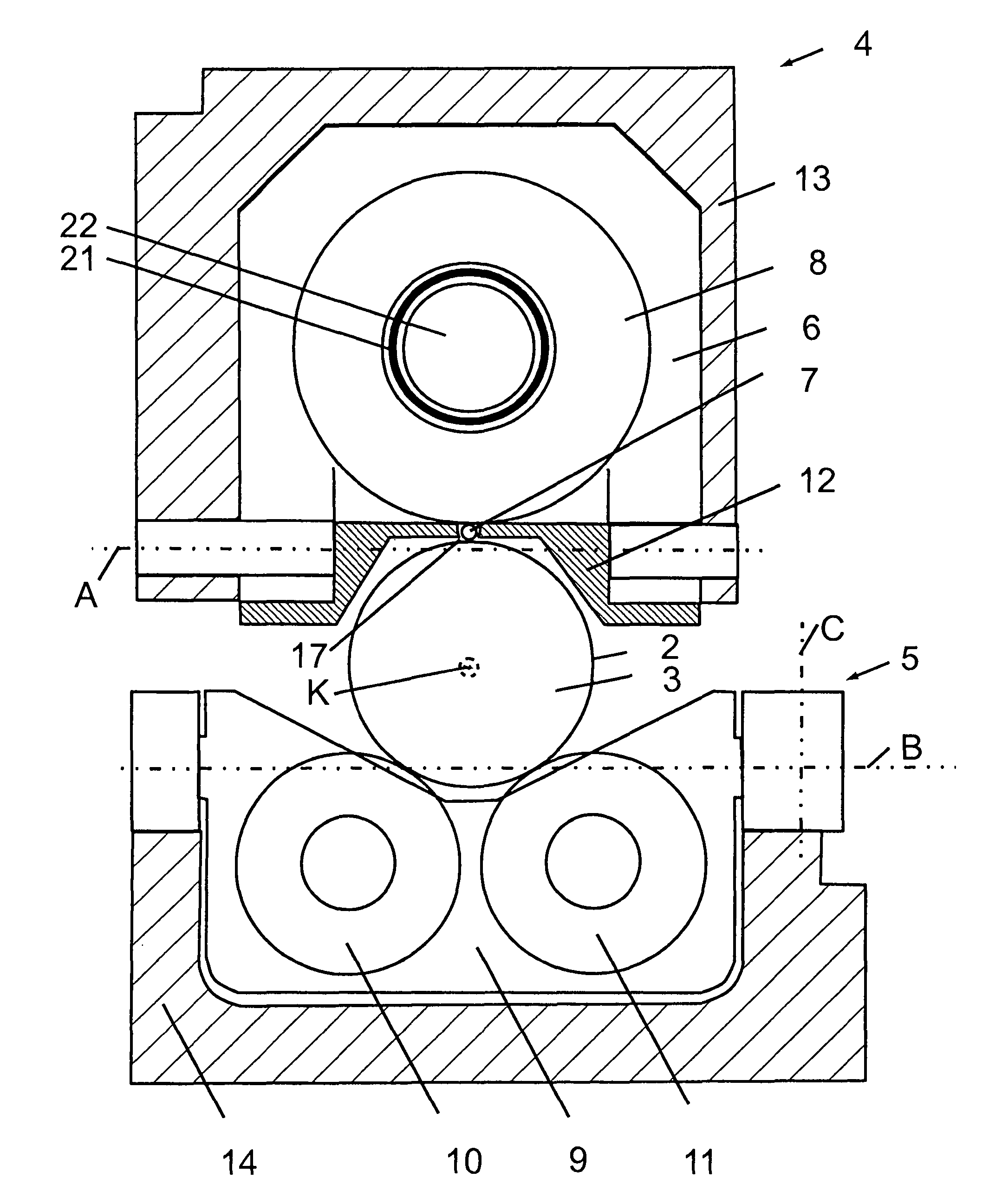
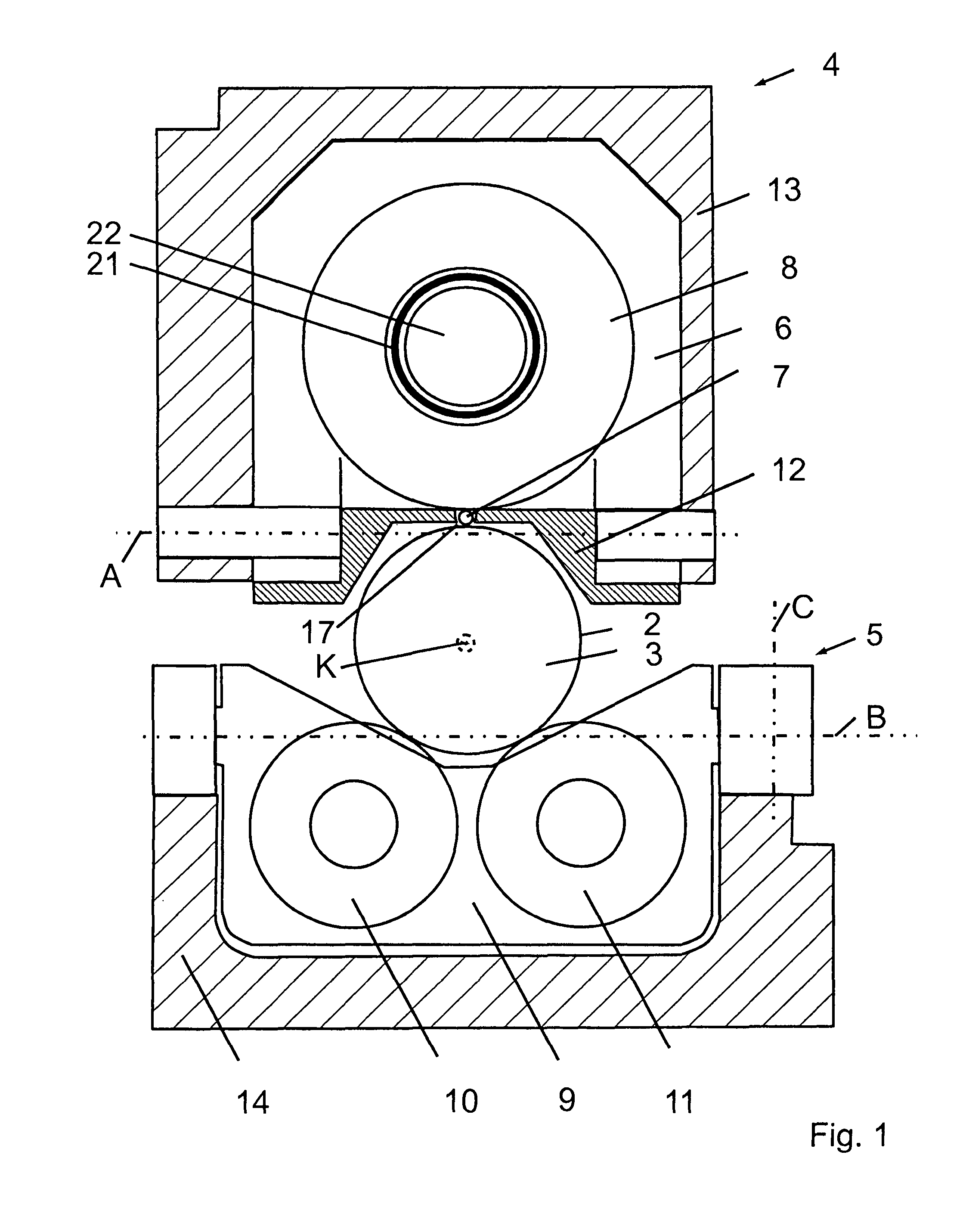
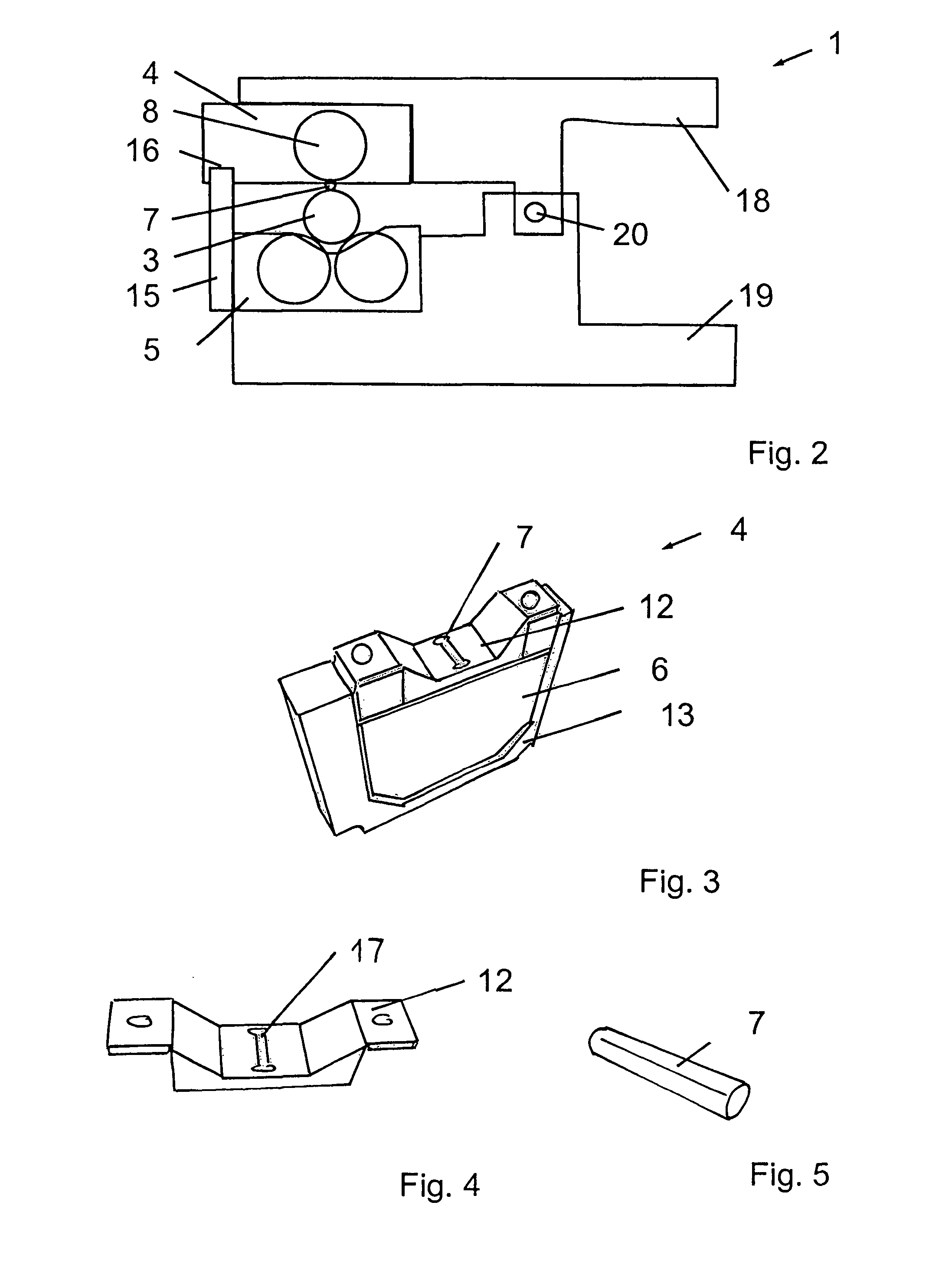
[0032]FIG. 1 shows a schematic diagram of a finishing roller head 4 and a support roller head 5 on a crankshaft 3 in a cross-section transversely to a crankshaft axis K of a crankshaft 3. One illustrated bearing surface 2 of the crankshaft 3 is a main bearing seat of the crankshaft 3. However, with the finishing roller head 4 it is also possible to process connecting rod bearings and journal bearings of the crankshaft 3 and other bearings. Orthogonally to the illustrated surface, the finishing roller head 4 and the support roller head 5 are designed to be so narrow that there are spaces with respect to the two crank cheeks which adjoin bearing surface 2. The support roller head 5 supports the crankshaft 3 against a rolling force exerted by the finishing roller head 4 through a roller finishing roller 7 on the crankshaft 3.

[0033]The finishing roller head 4 has a finishing roller head h...


PUM

PropertyMeasurementUnit
Diameteraaaaaaaaaa
Diameteraaaaaaaaaa
Distanceaaaaaaaaaa

Abstract

A rolling tool for the roller finishing of bearing surfaces of a crankshaft is pivotable around a crankshaft axis, with a finishing roller head and with a support roller head. In order to prevent damage to the guide mechanisms, the roller finishing roller is guided on all sides in a roller cage and the finishing roller head has a frame wherein it is mounted pivotably around a first pivot axis which is perpendicular to the crankshaft axis and parallel to a tangent on a working side of the roller finishing roller. Additionally or alternatively, the support roller head comprises a support roller frame in which the support roller housing is mounted pivotably around a second pivot axis perpendicular to the crankshaft axis and parallel to the first pivot axis, and around a third pivot axis perpendicular to the crankshaft axis and perpendicular to the first pivot axis.

Description

CROSS REFERENCE TO RELATED APPLICATIONS[0001]This application is a 371 U.S. National Stage of International Application No. PCT / DE2014 / 000392, filed Jul. 24, 2014. This application claims the benefit of German Patent Application No. 202013006779.9, filed Jul. 27, 2013. The disclosures of the above applications are incorporated herein by reference.FIELD[0002]The invention relates to a rolling tool for the roller finishing of bearing surfaces of a crankshaft which is pivotable around a crankshaft axis with a finishing roller head and a support roller head, wherein the finishing roller head has a roller finishing roller and a pressure roller which is mounted in a finishing roller head housing and which supports the roller finishing roller, and wherein the support roller head has two supporting rollers which are mounted in a supporting roller housing and with which the crankshaft can be supported against a rolling force acting on the crankshaft through the roller finishing roller.BACKGR...

Claims


Application Information

Patent Timeline
IPC IPC(8): B21H7/18
CPCB21H7/185B24B39/04B24B41/002B24B41/02B23P9/02B23P2700/07B24B5/42
Inventor HEIMANN, ALFREDMALDANER, JANDREY
Owner HEGENSCHEIDT MFD
Learn More