Variable pitch mounting for aircraft gas turbine engine

a gas turbine engine and variable pitch technology, applied in the direction of aircraft power plants, power plant construction, power plant types, etc., can solve the problems of engine yawing force, particularly acute problems, and aerodynamic load on each

Inactive Publication Date: 2016-06-16
GENERAL ELECTRIC CO
View PDF6 Cites 8 Cited by
  • Summary
  • Abstract
  • Description
  • Claims
  • Application Information

AI Technical Summary

Benefits of technology

The patent describes an aircraft gas turbine engine that can be pitched or rotated upward or downward to adjust its angle of attack for better performance during take-off and climb phases of flight. The engine is mounted on a pylon and a variable pitch mounting system is used to adjust the angle of the engine relative to the pylon. The system includes a variable length actuator that can change the length of the front and rear linkages that suspend the engine from the pylon. By adjusting the length of the actuator, the engine can be pitched or rotated to improve performance. The method can be used during take-off or climb phases of flight.

Problems solved by technology

For an airplane with an open-rotor or unducted fan gas turbine engine or turboprop engine, this poses particularly acute problems.
This has two undesirable consequences.
Firstly, the aerodynamic load on each blade will follow with the incidence change creating a cyclic variation in loading on the blade, and a yawing force on the engine.
Secondly, the noise generated by the airfoil passing through the air is sensitive to the incidence at the leading edge, a compromise in fan loading and / or efficiency may be required to compensate for the extra noise generated by the non-optimal fan blade leading edge incidence over parts of the circular path of the blade.
This leads to higher fuel consumption and / or weight.
Certain types and geometries of engine inlets allow the rotation of the aircraft to cause separation of the airflow in local regions of the inlet adversely affecting engine performance, and requiring additional robustness in the downstream airfoils to resist the fatigue loads induced by the separated airflow region.

Method used


Image

  • Variable pitch mounting for aircraft gas turbine engine
  • Variable pitch mounting for aircraft gas turbine engine
  • Variable pitch mounting for aircraft gas turbine engine

Examples


Embodiment Construction

[0030]Embodiments described herein are described in connection with ducted fan and open-rotor aircraft gas turbine engines. Examples include an unducted counter-rotatable front fan high bypass ratio engine, or UDF.

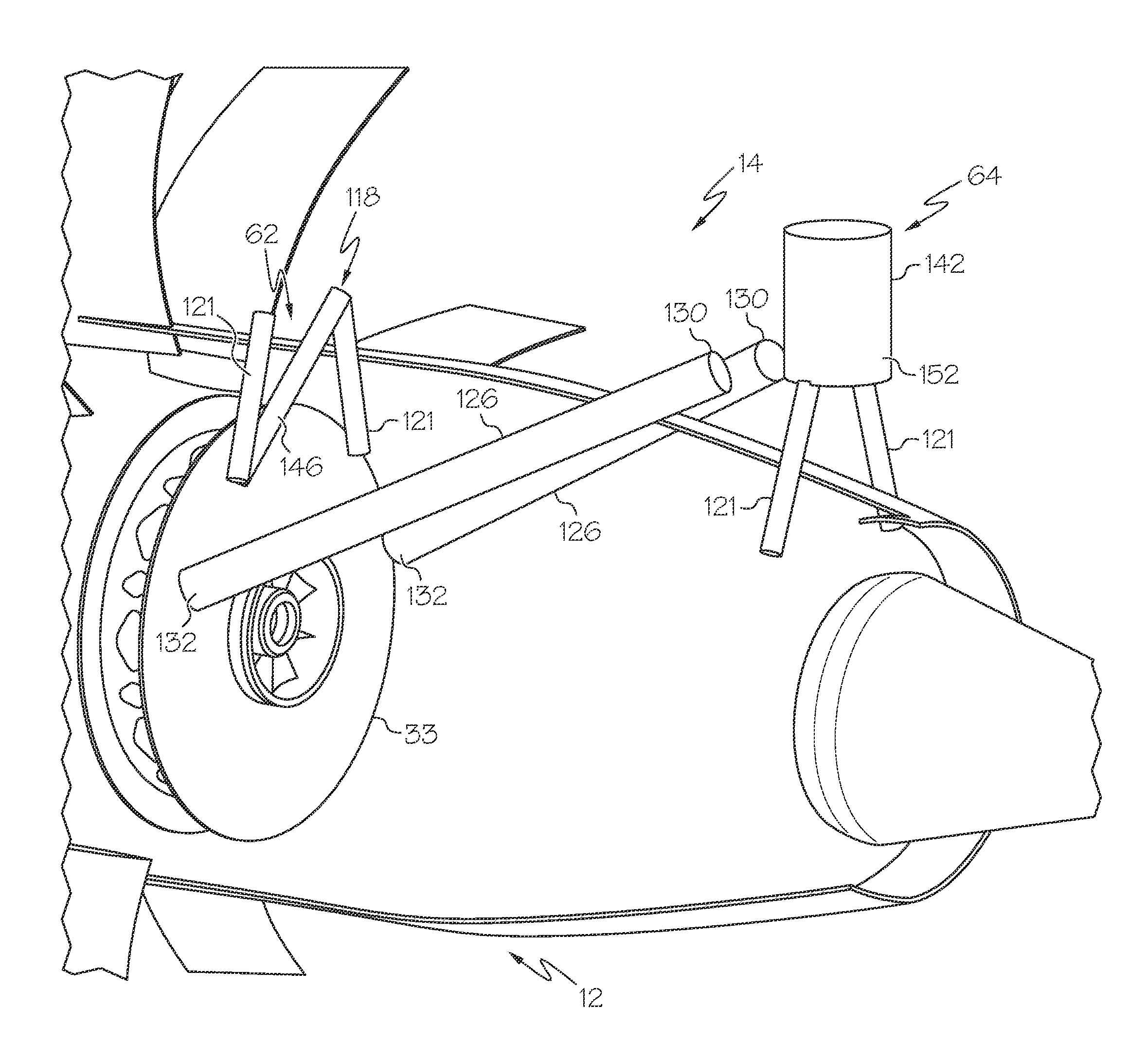
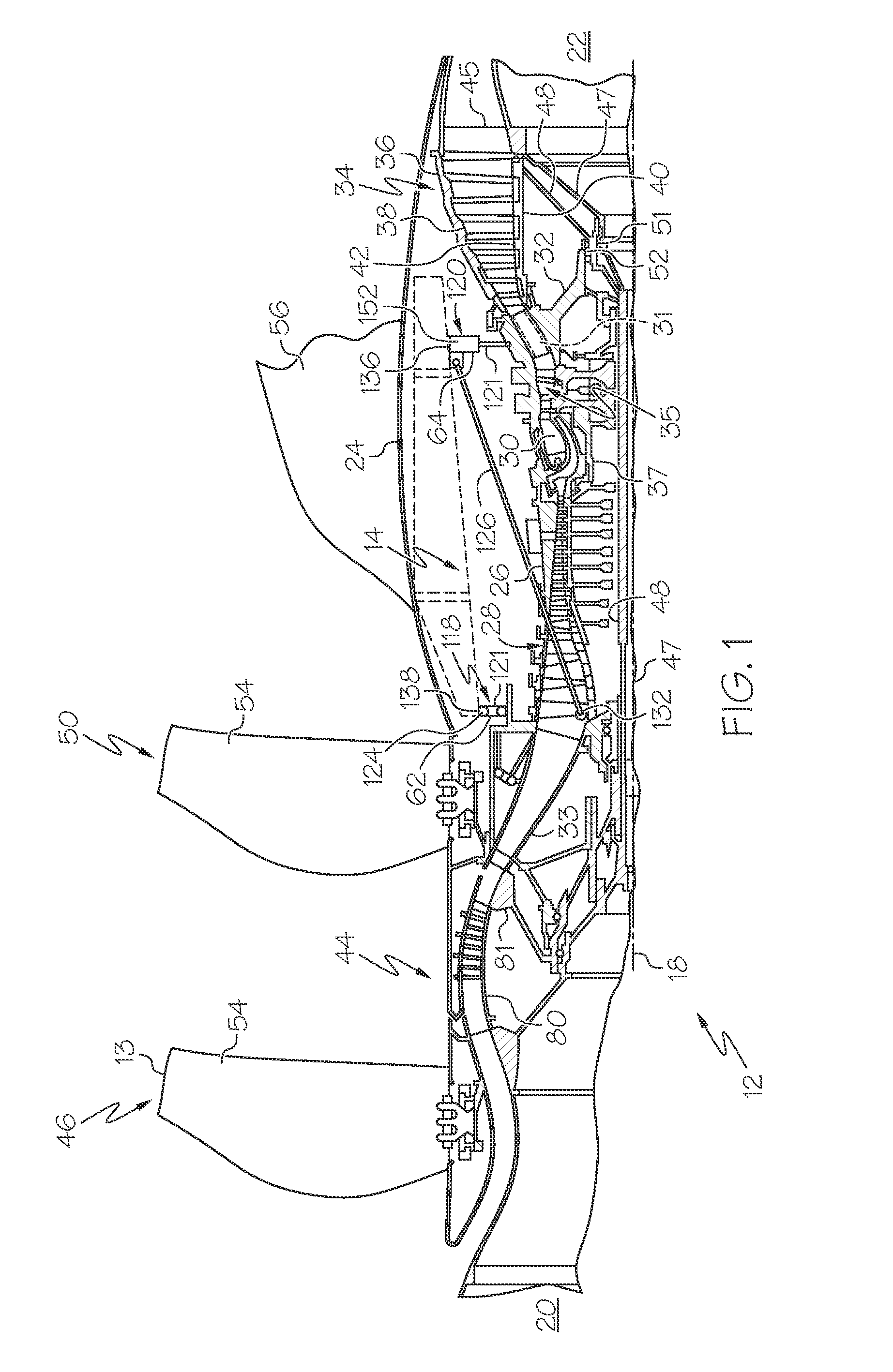
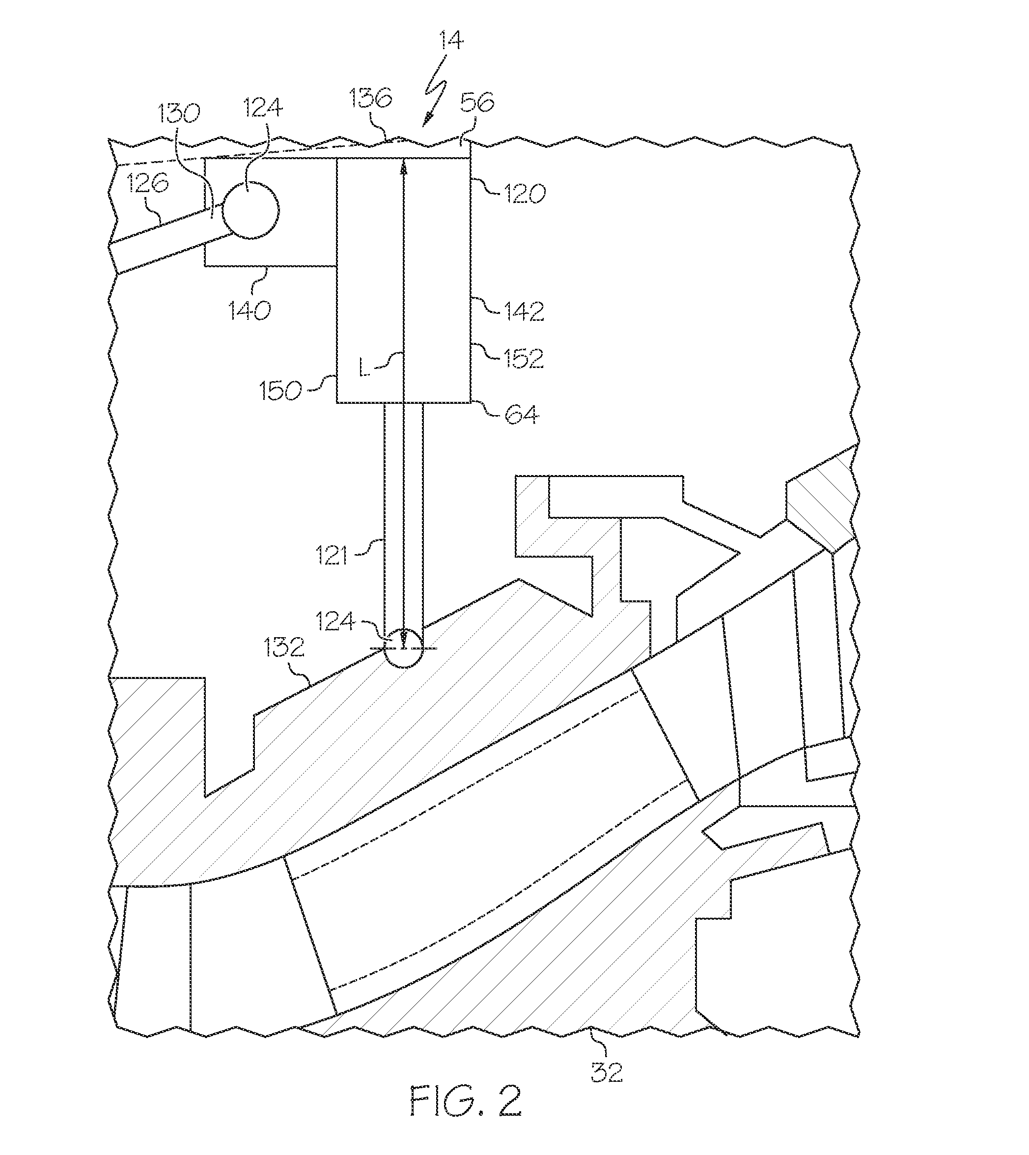
[0031]Illustrated in FIG. 1 is an exemplary aircraft gas turbine engine 12 and, more particularly, an unducted counter-rotatable front fan high bypass ratio gas turbine engine 12, also referred to herein as an open-rotor gas turbine engine. Unducted and open-rotor engines have open-fan blade tips 13 that are not radially outwardly bounded or surrounded by any fan casing or nacelle. The engine 12 is circumscribed about an engine centerline axis 18 and suitably designed to be mounted to a wing or fuselage of an aircraft (not shown) by a pylon 56. The engine 12 extends aftwardly or downstream from a forward or upstream end 20 and aft or downstream end 22 of the engine 12. Engine 12 includes an outer casing 24 disposed co-axially about centerline axis 18. The outer casing conv...


PUM


Abstract

Aircraft engine mounted to aircraft pylon with variable pitch mounting system includes variable length actuator disposed between engine and pylon for pitching engine relative to pylon. Spaced apart pylon front and rear mounts may pivotably mount front and rear stationary engine components of engine to front and rear mount positions on pylon. Front and rear linkages may vertically suspend engine from pylon with pivotable links disposed between pylon front and rear mounts and front and rear stationary engine components. One or more thrust links may be pivotably joined at link rear ends to pylon rear mount and at link forward ends to front support frame. Alternative mounting system may include support structure cantilevered off pylon for pivotably supporting engine and actuator substantially horizontally disposed between engine and pylon. Incidence angle between engine centerline axis and air streamlines may be adjusted by changing length of actuator.

Description

FIELD OF THE INVENTION[0001]The present invention relates generally to mounting aircraft engines to aircraft.DESCRIPTION OF RELATED ART[0002]Aircraft engines such as gas turbine engines may be mounted to an aircraft at various locations such as the wings, fuselage, or tail. Aircraft engines include gas turbine powered engines, electric engines, hybrid engines, and piston engines. The engine is typically mounted at axially spaced apart forward and aft or front and rear positions by corresponding forward and aft or front and rear mounts for carrying various loads to the aircraft. The loads typically include vertical loads such as the weight of the engine itself, axial thrust loads generated by the engine, lateral loads such as those due to wind buffeting, and roll loads or moments due to rotary operation of the engine. The mounts accommodate both axial and radial thermal expansion and contraction of the engine relative to the supporting pylon.[0003]U.S. Pat. No. 5,320,307, entitled “A...

Claims


Application Information

Patent Timeline
IPC IPC(8): B64D27/26B64C19/00B64D27/10B64D27/16
CPCB64D27/26B64D27/16B64D2027/005B64D27/10B64D2027/266B64C19/00B64D27/40B64D27/404
Inventor PRENTICE, IAN FRANCIS
Owner GENERAL ELECTRIC CO
Why Eureka
Try Eureka