Chlorine evolution anode

a technology of chlorine evolution and anode, applied in the direction of electrolysis components, multiple component coatings, electrolysis coatings, etc., can solve the problems of increasing the potential of the anode, increasing the electrolytic voltage, and reducing the service life and durability of the anod

Inactive Publication Date: 2016-06-16
DOSHISHA CO LTD
View PDF4 Cites 0 Cited by
  • Summary
  • Abstract
  • Description
  • Claims
  • Application Information

AI Technical Summary

Benefits of technology

[0049]The present invention provides the effects listed below.
1) The chlorine evolution anode of which the main reaction is to generate chlorine from an aqueous solution may lower the chlorine evolution potential when compared with that of a conventional anode. Therefore, in electrowinning, brine electrolysis, hydrochloric acid electrolysis and sea water electrolysis, etc., this anode is able to decrease an electrolytic voltage in an aqueous solution of a wide range of pH, thus making it possible to significantly lower an electric energy consumption rate.
3) In addition to the above-described effects, the present invention provides the effect to eliminate or reduce the work to remove the oxide or other chemical compounds which would be otherwise deposited and accumulated by a side reaction on the anode. Thus, the damage to the anode that would be caused by such work is restrained, thereby providing a prolonged service life of the anode.
4) In addition to the above-described effects, the present invention provides the effect to eliminate or decrease the work removing the oxide or other chemical compounds which would be otherwise deposited and accumulated on the anode by a side reaction. Thus, maintenance and replacement of the anode may be decreased or reduced. Further, a necessity for suspending electrolysis is restrained because the need for removing work is eliminated or decreased, thus making it possible to realize continuous and more stable electrolysis.
6) Further, it is possible to prevent metal which has grown non-uniformly on the cathode from reaching and short-circuiting the anode due to the above-described reasons, thereby resulting in a failure of electrowinning. Still further, metal is prevented from growing non-uniformly and in a dendrite form on the cathode. It is therefore possible to decrease the distance between the anode and the cathode, and restrain an increase in electrolytic voltage by ohmic loss of an electrolytic solution.
7) Further, since various problems that would be otherwise caused by the deposits on the anode resulting from a side reaction are resolved as described above, it is possible to continuously perform stable electrolysis and decrease maintenance and management work. And, it is also possible to easily perform product management of metal obtained by electrowinning. Still further, it is possible to decrease the cost of the anode in long-term electrolysis.
8) Furthermore, according to the present invention, when compared with a conventional titanium electrode with a catalytic layer containing iridium oxide formed thereon, use of ruthenium oxide reduces the cost of the catalytic layer; and a reduced thermal decomposition temperature reduces the cost of the process of forming the catalytic layer as well.

Problems solved by technology

However, since cobalt oxyhydroxide has a low catalytic activity for chlorine evolution, it inhibits the chlorine evolution reaction on the anode, increases a potential of the anode as a result, and causes an increase in electrolytic voltage.
The above-described deposition and accumulation of a metal oxide on the anode due to the side reaction raise the electrolytic voltage and at the same time cause a reduction in service life and durability of the anode.

Method used


Image

  • Chlorine evolution anode
  • Chlorine evolution anode

Examples


example 1

[0053]A commercially available titanium plate (5 cm in length, 1 cm in width, 1 mm in thickness) was immersed and etched in a 10% oxalic acid solution at 90° C. for 60 minutes and then washed and dried. Next, prepared was a coating solution which was obtained by adding ruthenium trichloride trihydrate (RuCl3.3H2O) and tantalum pentachloride (TaCl5) to a butanol (n-C4H9OH) solution containing 6 vol % concentrated hydrochloric acid so that the mole ratio of ruthenium to tantalum is 90:10 and the total of ruthenium and tantalum is 50 g / L in terms of metal. This coating solution was applied to the titanium plate dried as mentioned above, dried at 120° C. for 10 minutes, and then thermally decomposed for 20 minutes in an electric furnace that was held at 260° C. This series of application, drying, and thermal decomposition was repeated five times in total in order to prepare a chlorine evolution anode of Example 1, the anode having a catalytic layer formed on the titanium plate that was ...
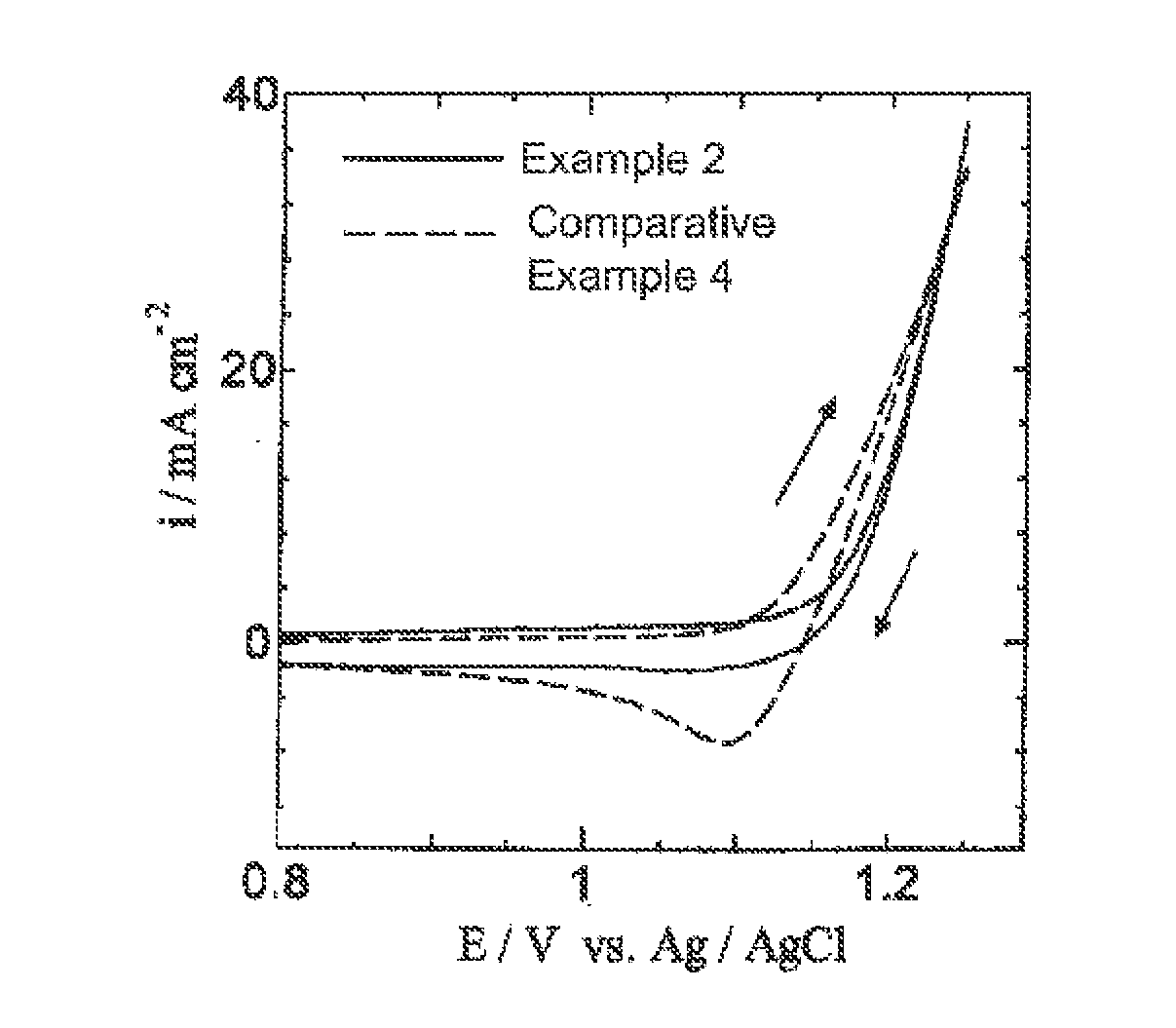
example 2

[0065]A commercially available titanium plate (5 cm in length, 1 cm in width, 1 mm in thickness) was immersed and etched in a 10% oxalic acid solution at 90° C. for 60 minutes and then washed and dried. Next, prepared was a coating solution which was obtained by adding ruthenium trichloride trihydrate (RuCl3.3H2O) and tantalum pentachloride (TaCl5) to a butanol (n-C4H9OH) solution containing 6 vol % concentrated hydrochloric acid so that a mole ratio of ruthenium to tantalum was 30:70 and a total of ruthenium and tantalum was 50 g / L in terms of metal. This coating solution was applied to the titanium plate dried as mentioned above, dried at 120° C. for 10 minutes and then, thermally decomposed for 20 minutes in an electric furnace that was held at 280° C. This series of application, drying and thermal decomposition was repeated five times in total in order to prepare a chlorine evolution anode in which a catalytic layer was formed on the titanium plate that was a conductive substrat...
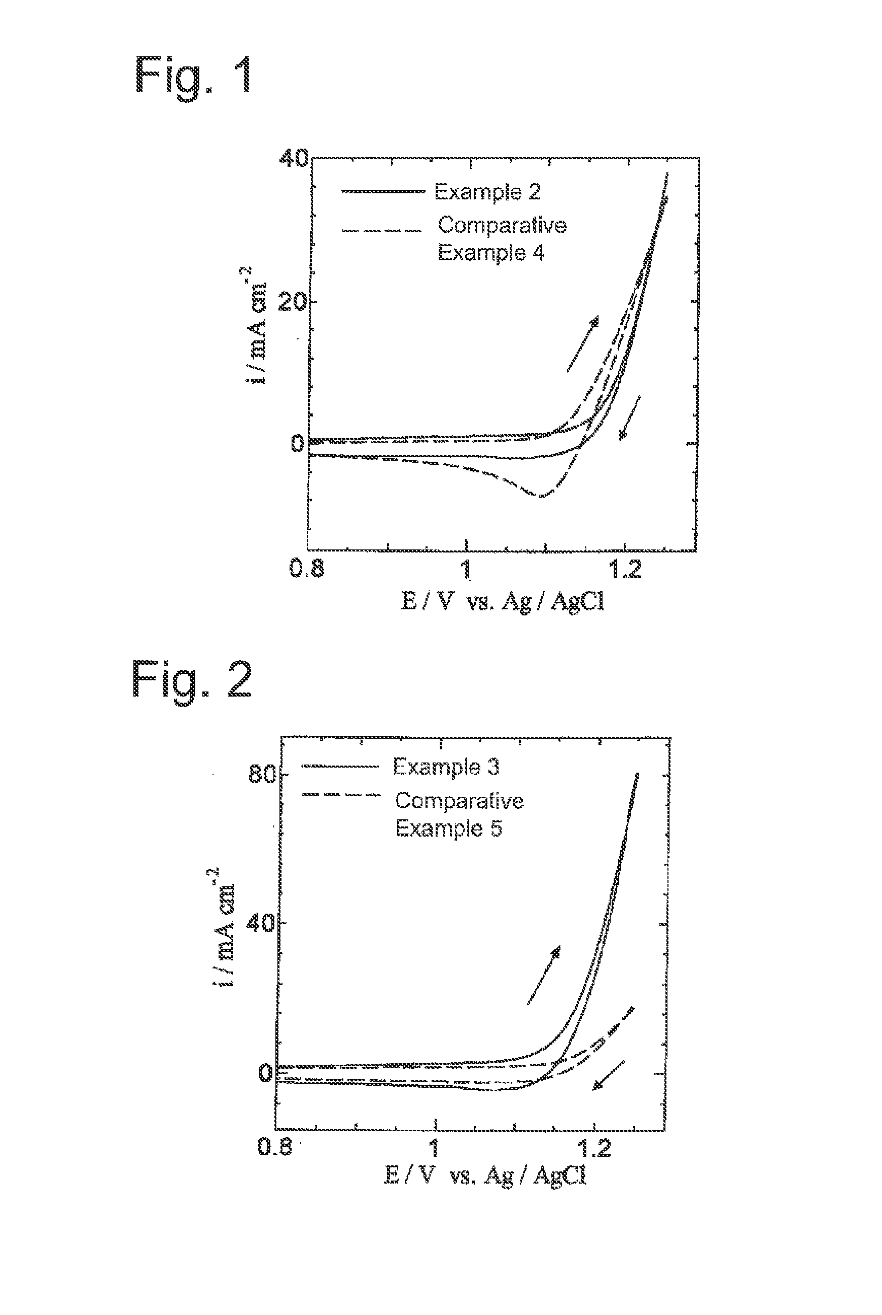
example 3

[0070]The chlorine evolution anode of Example 2 was used to measure cyclic voltammograms under the same conditions except that the cobalt electrowinning solution of Example 2 was changed to a hydrochloric acid electrolytic solution, the pH of which was adjusted to 1.6 by adding only hydrochloric acid to distilled water and the scan rate was changed to 50 mV / s.


PUM

PropertyMeasurementUnit
temperatureaaaaaaaaaa

Abstract

Provided is a chlorine evolution method which includes contacting an anode with chloride based aqueous solution and generating chlorine as a main reaction at the anode, in which a main reaction of the anode is chlorine evolution, and the chlorine evolution anode which is low in potential of the anode for chlorine evolution, thereby being able to decrease an electrolytic voltage and lower an electric energy consumption rate. The chlorine evolution anode of the present invention is a chlorine evolution anode in which chlorine evolution from an aqueous solution is a main reaction of the anode and also in which a catalytic layer containing amorphous ruthenium oxide and amorphous tantalum oxide is formed on a conductive substrate.

Description

CROSS REFERENCE TO RELATED APPLICATIONS[0001]This is a continuation of U.S. application Ser. No. 14 / 344,757 filed Mar. 13, 2014, which is a National Stage of International Application No. PCT / JP012 / 2072236 filed Aug. 31, 2012, claiming priority based on Japanese Patent Application No. 2011-199257 filed Sep. 13, 2011, the contents of all of which are incorporated herein by reference in their entirety.TECHNICAL FIELD[0002]The present invention relates to a chlorine evolution anode which is used in electrowinning a desired metal at a cathode by electrolysis and also to a chlorine evolution anode which is used in generating chlorine from a chloride based aqueous solution by brine electrolysis, hydrochloric acid electrolysis, sea water electrolysis, etc. More specifically, the present invention relates to a chlorine evolution anode which is used in electrowinning, brine electrolysis, hydrochloric acid electrolysis, sea water electrolysis, etc., in which an aqueous solution is used as an ...

Claims


Application Information

Patent Timeline
Patent Type & Authority Applications(United States)
IPC IPC(8): C25B11/04C25B1/26
CPCC25B11/0484C25B11/0405C25B1/26C02F1/4674C02F2001/46142C02F2103/08C02F2001/46147C25C7/02C25B11/051C25B11/093C25B11/097
Inventor MORIMITSU, MASATSUGU
Owner DOSHISHA CO LTD
Why Eureka
Try Eureka