Target Characterization Based on Persistent Collocation of Multiple Specks of Light in Time Series Imagery

a time series imagery and target technology, applied in the field of particle, cell and bead-based assay applications, can solve the problems of limited multi-speck assays, achieve high sensitivity, simple and computationally efficient characterization, and rapid detection of targets

Inactive Publication Date: 2016-06-16
THE BOARD OF TRUSTEES OF THE LELAND STANFORD JUNIOR UNIV
View PDF7 Cites 5 Cited by
  • Summary
  • Abstract
  • Description
  • Claims
  • Application Information

AI Technical Summary

Benefits of technology

[0008]There remains a need for better methods that will allow rapid detection of targets (such as molecules, organelles and cells) with high sensitivity even in multiplex assays in which different targets are identified in the same sample during the same process. Techniques are provided for simple and computational efficient characterization of targets based on multiple imaging conditions.
[0020]In a third set of embodiments, a non-transitory computer-readable medium carries one or more sequences of instructions, wherein execution of the one or more sequences of instructions by one or more processors causes an apparatus to obtain multiple time series of images. Each image represents light measured in an interrogation area of a fluid under conditions that cause only one optical marker type of at least two optical marker types to emit or scatter light. Each different time series of images indicates light measured from a different single optical marker type of the at least two optical marker types. The at least two optical marker types are configured to collocate with a single target type. The instructions further cause the apparatus to determine, in the time series of images, a path of a speck of light from an individual optical marker of a first optical marker type of the at least two optical marker types. The instructions still further cause the apparatus to determine whether the path corresponds to the target type based on persistence of collocation of the speck of light from the individual optical marker of the first optical marker type with a speck of light from each of other optical marker types different from the first optical marker type.
[0021]In a fourth set of embodiments, a system includes at least one processor and at least one memory including one or more sequences of instructions. The at least one memory and the one or more sequences of instructions are configured to, with the at least one processor, cause an apparatus to obtain multiple time series of images. Each image represents light measured in an interrogation area of a fluid under conditions that cause only one optical marker type of at least two optical marker types to emit or scatter light. Each different time series of images indicates light measured from a different single optical marker type of the at least two optical marker types. The at least two optical marker types are configured to collocate with a single target type. The instructions further cause the apparatus to determine, in the time series of images, a path of a speck of light from an individual optical marker of a first optical marker type of the at least two optical marker types. The instructions still further cause the apparatus to determine whether the path corresponds to the target type based on persistence of collocation of the speck of light from the individual optical marker of the first optical marker type with a speck of light from each of other optical marker types different from the first optical marker type.

Problems solved by technology

Due to the nature of aggregates, multiplexing using this assay is limited.

Method used


Image

  • Target Characterization Based on Persistent Collocation of Multiple Specks of Light in Time Series Imagery
  • Target Characterization Based on Persistent Collocation of Multiple Specks of Light in Time Series Imagery
  • Target Characterization Based on Persistent Collocation of Multiple Specks of Light in Time Series Imagery

Examples


Embodiment Construction

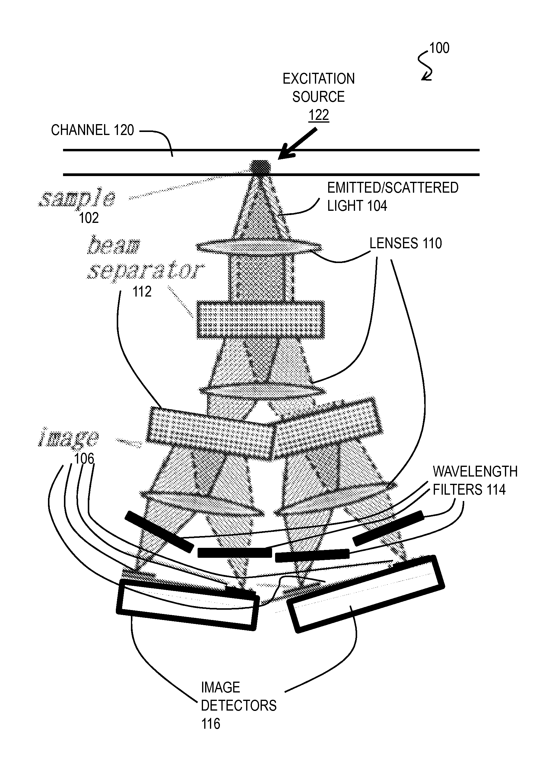
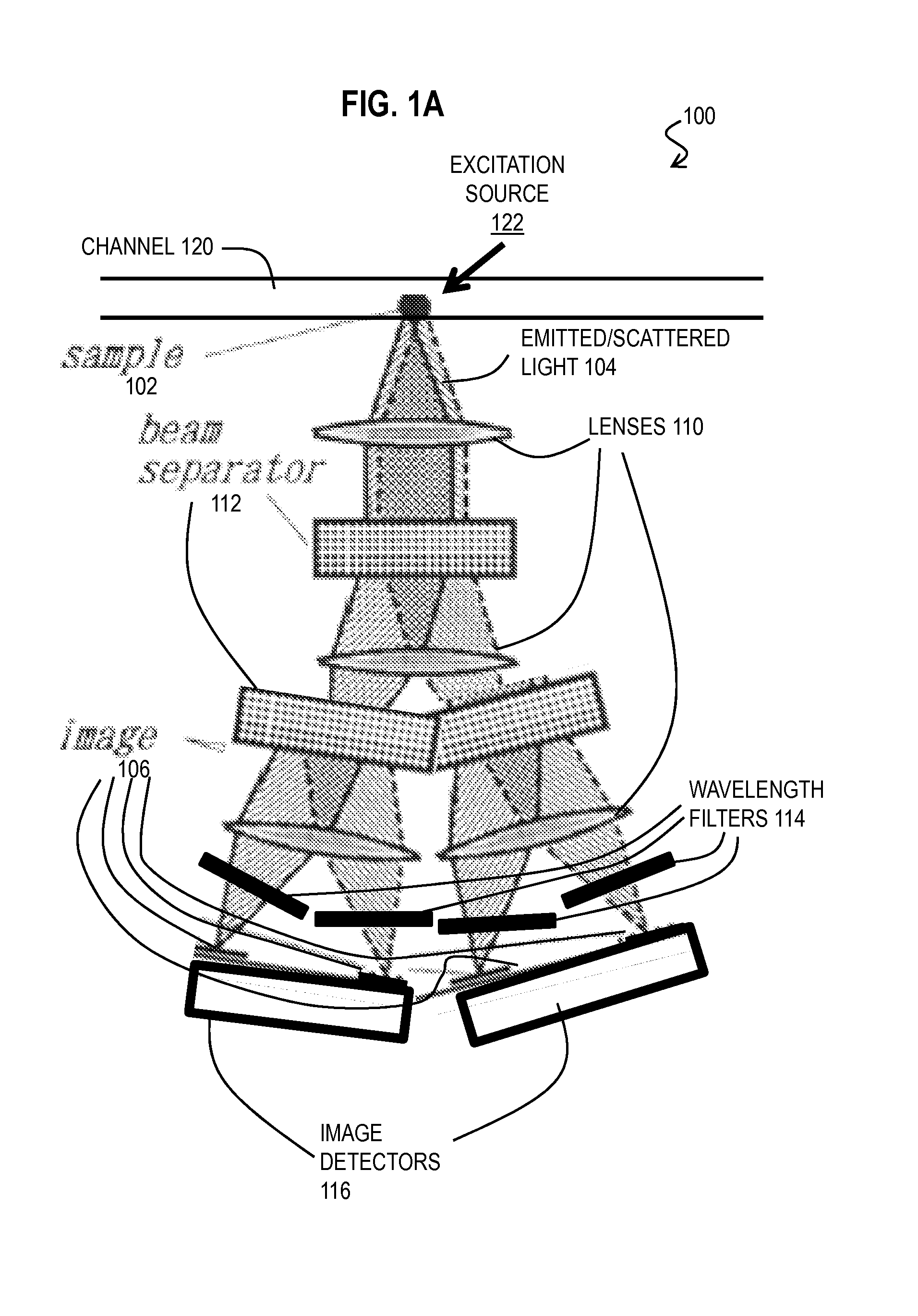
[0042]A method, system and kit are described for characterizing targets, including microparticles, based on persistent collocation of multiple specks of light in time series imagery. In the following description, for the purposes of explanation, numerous specific details are set forth in order to provide a thorough understanding of the present invention. It will be apparent, however, to one skilled in the art that the present invention may be practiced without these specific details. In other instances, well-known structures and devices are shown in block diagram form in order to avoid unnecessarily obscuring the present invention.

[0043]Some embodiments of the invention are described below in the context of fluorescent beads as optical markers and a DNA molecule type as a target type. However, the invention is not limited to this context. In other embodiments the target types are other DNA types or other oligonucleotide types or protein types or cell types or organelle types or othe...


PUM

PropertyMeasurementUnit
wavelengthsaaaaaaaaaa
sizeaaaaaaaaaa
diameteraaaaaaaaaa

Abstract

Techniques for characterizing targets include obtaining multiple time series of images. Each image represents light measured in an interrogation area under conditions that cause only one optical marker type of at least two optical marker types to emit or scatter light. Each different time series indicates light measured from a different single optical marker type. The at least two optical marker types are configured to collocate with a single target type. The techniques include determining a path of a speck of light from an individual optical marker of a first optical marker type. The techniques also include determining whether the path corresponds to the target type based on persistence of collocation of a speck of light from each of the other optical marker types. The collocation can be based on maximum correlation in a portion of contemporaneous images. The persistence can be long compared to random separation times.

Description

CROSS-REFERENCE TO RELATED APPLICATIONS[0001]This application claims benefit of Provisional application 61 / 822,340, filed May 11, 2013, the entire contents of which are hereby incorporated by reference as if fully set forth herein, under 35 U.S.C. §119(e).BACKGROUND OF THE INVENTION[0002]Accompanying the growing number of particle, cell, and bead-based assay applications, particle and cell analysis methods have become more rigorous and sophisticated. The two most frequently cited techniques are likely flow cytometry (FCM) and laser-scanning cytometry (LSC). Flow cytometry is a workhorse technology used routinely in immunology, pathology, and hemotology. FCM performs a single high content multiparametric measurement for thousands of particles in minutes or less. (Here “particles” denote living and fixed cells and / or micron-scale fluorescent beads such as Luminex beads.) Microparticles are particles with a largest dimension less than about 1000 microns (1 micron, also called a microme...

Claims


Application Information

Patent Timeline
Patent Type & Authority Applications(United States)
IPC IPC(8): G01N21/64G01N33/58G01N33/53G06T7/20C12Q1/68
CPCG01N21/6428G06T7/20C12Q1/6825G06T2207/30204G01N33/582G01N2021/6439G01N2021/6441G01N33/53G01N15/1429G01N2015/1006G01N15/1459G01N15/1463G01N2015/1075G01N15/1484B01L3/502715
Inventor ROGACS, ANITAMARSHALL, LEWIS A.SANTIAGO, JUAN G.
Owner THE BOARD OF TRUSTEES OF THE LELAND STANFORD JUNIOR UNIV
Why Eureka
Try Eureka