Differential-type MEMS acoustic transducer

a technology of acoustic transducers and different types, applied in the direction of transducer types, electrical equipment, semiconductor electrostatic transducers, etc., can solve the problems of difficult to obtain, poor rejection of any common-mode disturbance component, and the ability to increase the signal-to-noise ratio as desired

Active Publication Date: 2016-06-16
STMICROELECTRONICS SRL
View PDF3 Cites 21 Cited by
  • Summary
  • Abstract
  • Description
  • Claims
  • Application Information

AI Technical Summary

Problems solved by technology

This single-ended circuit configuration has some drawbacks, amongst which poor rejection in regard to any common-mode disturbance component, for example deriving from the supply noise or from crosstalk, due to near devices having time-varying signals.
Even though the differential configuration described with reference to FIG. 3 enables improvement of the disturbance rejection capacity, not even this makes it

Method used


Image

  • Differential-type MEMS acoustic transducer
  • Differential-type MEMS acoustic transducer
  • Differential-type MEMS acoustic transducer

Examples


Embodiment Construction

[0040]A possible solution for increasing the signal-to-noise ratio of the MEMS acoustic transducer may envisage increase of the physical area of the transducer, i.e., the surface of the corresponding membrane and of the back plate. In fact, known statistical laws (here not discussed in detail) state that, in order to improve the signal-to-noise ratio (SNR) of an electronic component, its physical area may be increased accordingly.

[0041]For example, the signal-to-noise ratio (SNR) of a MEMS acoustic transducer of a capacitive type may be increased by approximately 3 dB by doubling the area of the corresponding membrane and of the corresponding back plate.

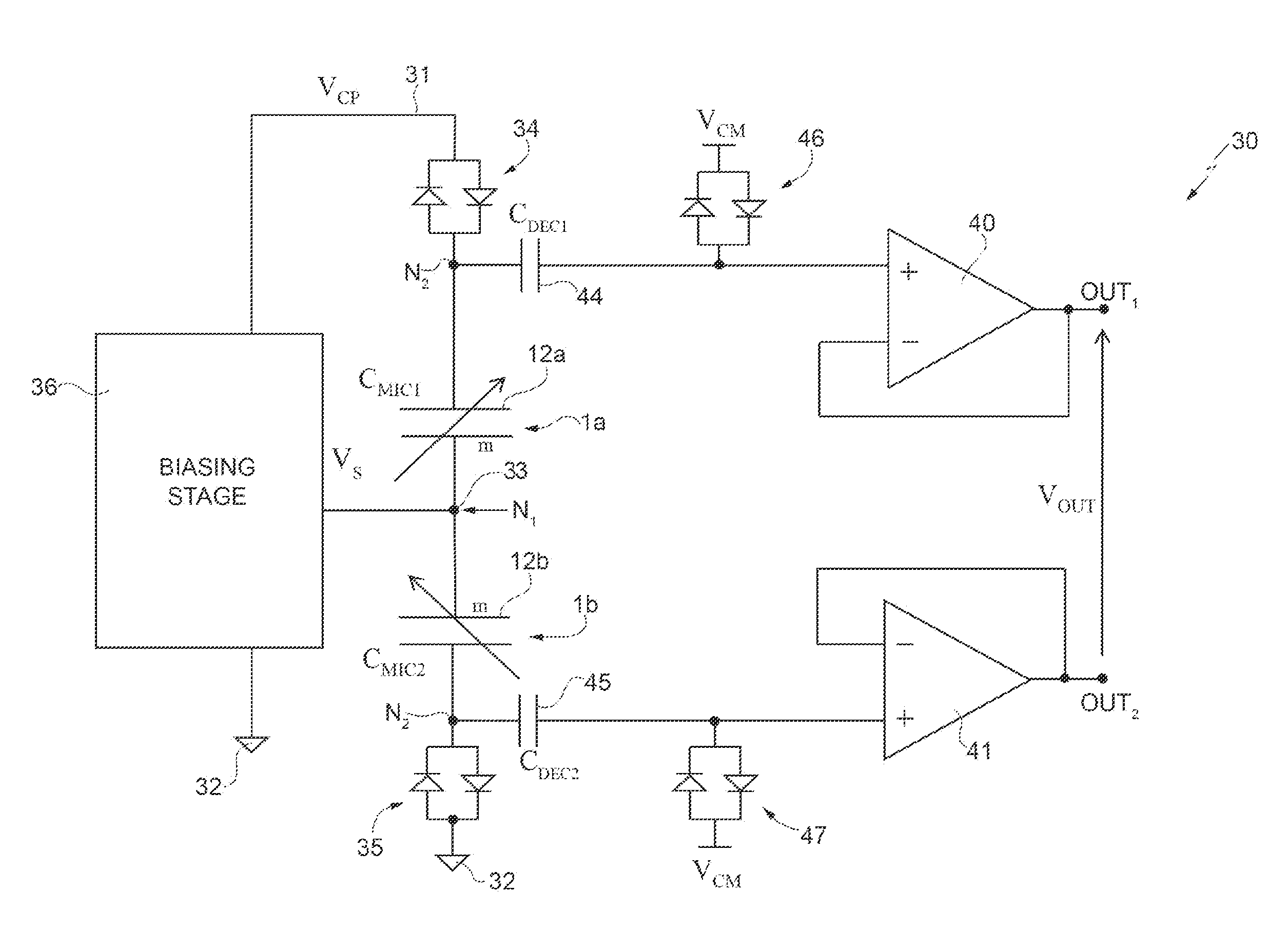
[0042]A possible solution may thus envisage “duplicating” or “doubling” the micromechanical structure of the MEMS acoustic transducer. However, in order to prevent problems of mechanical strength and consequent risks of failure, two micromechanical detection structures may be provided, each substantially similar to the micromechanica...


PUM


Abstract

A MEMS acoustic transducer has: a detection structure, which generates an electrical detection quantity as a function of a detected acoustic signal; and an electronic interface circuit, which is operatively coupled to the detection structure and generates an electrical output quantity as a function of the electrical detection quantity. The detection structure has a first micromechanical structure of a capacitive type and a second micromechanical structure of a capacitive type, each including a membrane that faces and is capacitively coupled to a rigid electrode and defines a respective first detection capacitor and second detection capacitor; the electronic interface circuit defines an electrical connection in series of the first detection capacitor and second detection capacitor between a biasing line and a reference line, and further has a first single-output amplifier and a second single-output amplifier, which are coupled to a respective one of the first detection capacitor and the second detection capacitor and have a respective first output terminal and second output terminal, between which the electrical output quantity is present.

Description

BACKGROUND[0001]1. Technical Field[0002]The present disclosure relates to a MEMS (Micro-Electro-Mechanical System) acoustic transducer of a differential type.[0003]2. Description of the Related Art[0004]As is known, a MEMS acoustic transducer, for example a microphone of a capacitive type, generally comprises a micromechanical detection structure, which is designed to transduce acoustic pressure waves into an electrical quantity (in particular a capacitive variation), and an electronic reading interface, which is designed to carry out appropriate processing operations (amongst which amplification and filtering operations) on the same electrical quantity to provide an electrical output signal (for example, a voltage).[0005]The micromechanical structure in general comprises a mobile electrode, provided as a diaphragm or membrane, arranged facing a fixed electrode, at a small distance of separation (the so-called “air gap”), for providing the plates of a detection capacitor with capaci...

Claims


Application Information

Patent Timeline
IPC IPC(8): H04R19/00H04R19/02
CPCH04R19/005H04R19/02H04R2499/15H04R2499/11H04R2201/003
Inventor NICOLLINI, GERMANOADORNO, SILVIABARBIERI, ANDREABARBIERI, FEDERICACONTI, SEBASTIANOMARINO, EDOARDOPERNICI, SERGIO
Owner STMICROELECTRONICS SRL
Why Eureka
Try Eureka