High-efficiency molten carbonate fuel cell system and method

a fuel cell and high-efficiency technology, applied in the direction of fuel cells, fuel cell grouping, fuel cells, etc., can solve the problems of material and cost disadvantages, and achieve the effect of increasing electrical power generation

Active Publication Date: 2016-06-23
FUELCELL ENERGY INC
View PDF1 Cites 11 Cited by
  • Summary
  • Abstract
  • Description
  • Claims
  • Application Information

AI Technical Summary

Benefits of technology

[0012]FIG. 1 shows a conventional fuel cell system as described in the '458 patent, which outputs partially-spent fuel exhaust from a topping fuel cell stack A to a bottoming fuel cell stack B. The stack A includes a first cathode side 100 and a first anode side 105. The stack B includes a second cathode side 110 and a second anode side 115. The first anode side 105 is coupled to an anode booster blower 120 which increases the pressure of the hydrogen rich exhaus

Problems solved by technology

Additionally, this system requires a high temperature air-to-a

Method used


Image

  • High-efficiency molten carbonate fuel cell system and method
  • High-efficiency molten carbonate fuel cell system and method
  • High-efficiency molten carbonate fuel cell system and method

Examples


Embodiment Construction

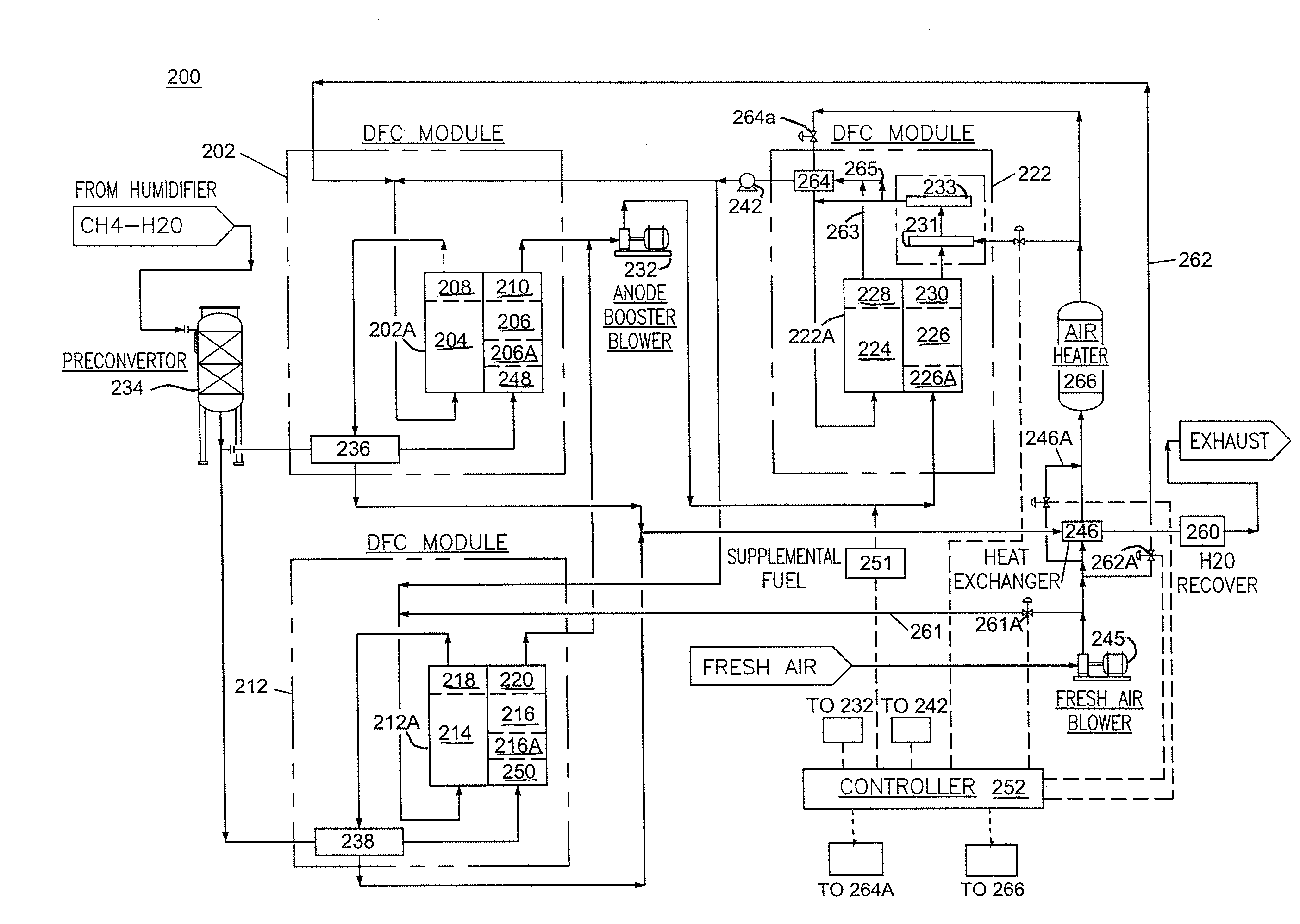
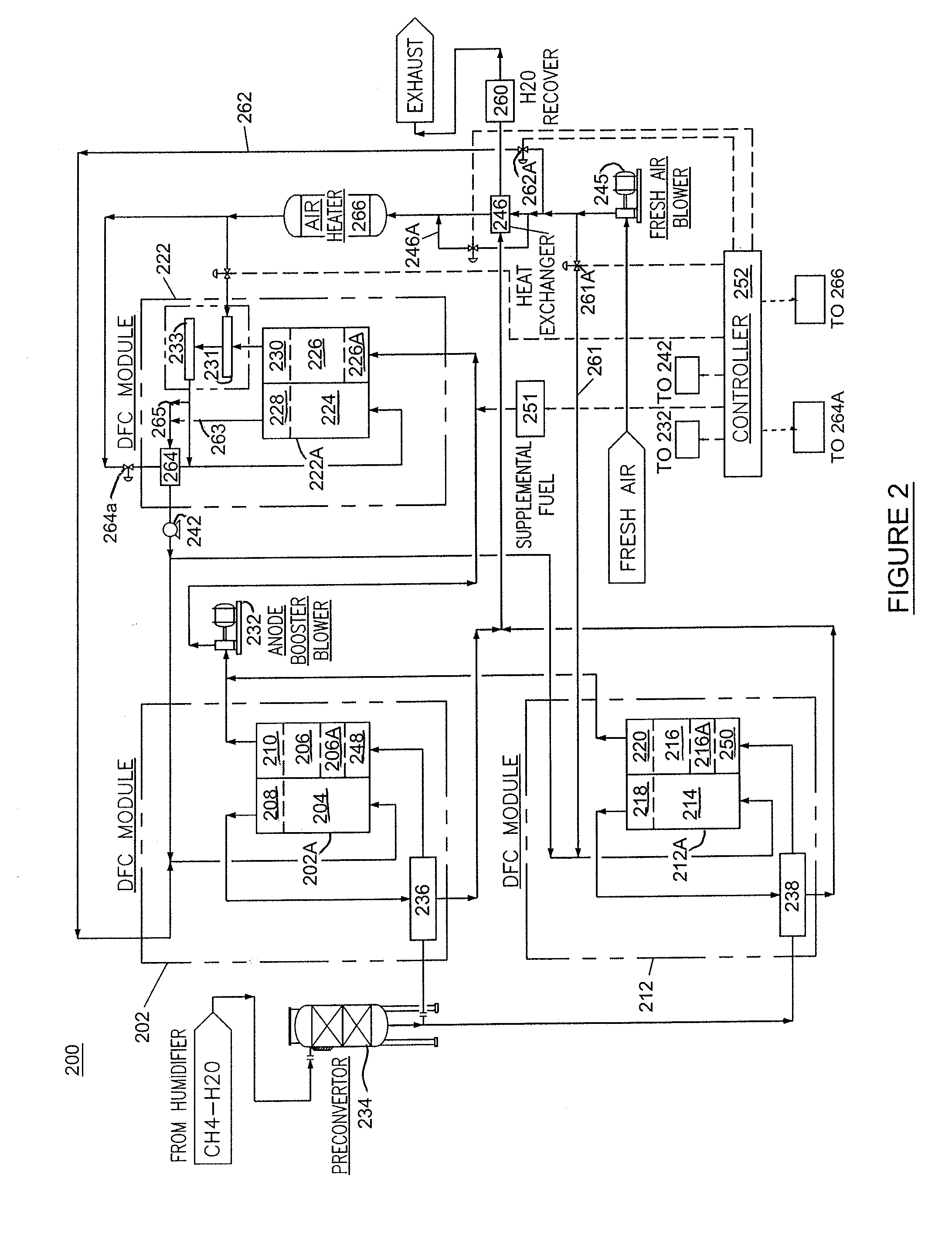
[0032]As shown and described below, the present invention provides a cost-effective, modular fuel cell system, in which higher overall fuel utilization and higher electrical power output and conversion system efficiency are achieved while maintaining thermal balance within the fuel cells. In accordance with the present invention, the fuel cell system includes a plurality of fuel cell stacks or a plurality of fuel cell stack modules including topping stack(s) or topping stack module(s) and bottoming stack(s) or bottoming stack module(s), and wherein the topping stack(s) / module(s) receive fresh fuel and partially spent fuel from the exhaust of the topping fuel cell stack(s) / module(s) is supplied to the bottoming fuel cell stack(s) / module(s). In the configuration of the system of the present invention, fuel utilization in the topping and bottoming fuel cell stacks / modules are controlled within desired limits while still increasing the overall fuel utilization and electrical efficiency ...


PUM


Abstract

A high efficiency fuel cell system comprising a topping fuel cell assembly comprising a topping cathode portion and a topping anode portion; and a bottoming fuel cell assembly comprising a bottoming cathode portion and a bottoming anode portion, wherein the bottoming anode portion receives anode exhaust output from the topping anode portion and the topping cathode portion receives cathode exhaust from the bottoming cathode portion, and wherein the topping fuel cell assembly has a greater number of fuel cells than the bottoming fuel cell assembly so that the topping fuel cell assembly utilizes more fuel than the bottoming fuel cell assembly.

Description

BACKGROUND OF THE INVENTION[0001]This invention relates to fuel cell power production systems and, in particular, to a multi-stack high-efficiency fuel cell system and method of operating same.[0002]A fuel cell is a device which directly converts chemical energy stored in hydrocarbon fuel into electrical energy by means of an electrical reaction. Generally, a fuel cell comprises an anode and a cathode separated by an electrolyte matrix, which conducts electrically charged ions. In order to produce a useful power level, a number of individual fuel cells are stacked in series with an electrically conductive separator plate between each cell.[0003]In building fuel cell systems, individual fuel cells are stacked together to form a fuel cell stack. The number of fuel cells determines the power rating of the fuel cell stack. To provide systems with higher power ratings, a number of fuel cell stacks are utilized and the outputs of the fuel cell stacks are combined to provide the desired po...

Claims


Application Information

Patent Timeline
IPC IPC(8): H01M8/14H01M8/24H01M8/04
CPCH01M8/141H01M8/0491H01M2008/147H01M8/04156H01M8/249H01M8/04104H01M8/2465H01M8/04089H01M8/04731H01M8/04753Y02E60/50
Inventor LAMBRECH, MATTHEWFAROOQUE, MOHAMMADJUHAS, CARLAJAHNKE, FRED C.VENKATARAMAN, RAMAKRISHNANQUATANNENS, MICHAEL L.
Owner FUELCELL ENERGY INC
Why Eureka
Try Eureka