Method for determining reduction factor of bearing capacity of axial load cylindrical shell structure

a technology of axial load and bearing capacity, applied in the field of stability analysis, can solve the problems of insufficient physical method of determining the knockdown factor in consideration of the realistic worst imperfections, the actual load-carrying capacity of the structure estimated on the basis of a perfect model theory or data to be much smaller than the actual condition, and the inability to provide a physical method for determining the knockdown factor , to achieve the effect of convenient verification, more physical, and higher fidelity and reliability

Active Publication Date: 2016-06-30
DALIAN UNIV OF TECH
View PDF0 Cites 15 Cited by
  • Summary
  • Abstract
  • Description
  • Claims
  • Application Information

AI Technical Summary

Benefits of technology

[0006]In view of the above-described problems, it is one objective of the invention to provide a method for determining a knockdown factor of load-carrying capacity of a cylindrical shell subjected to axial compression based on the combination of the perturbation loads that represents the realistic worst imperfection. The method introduces the multiple dimple imperfections, on the basis of optimization technologies such as an enumeration method, genetic algorithm and surrogate-based optimization, and yields the combination of a finite number of perturbation loads that causes the realistic worst imperfection, thereby determining the knockdown factor of the load-carrying capacity of the cylindrical shell. Compared with conventional methods for evaluating imperfection sensitivity based on experimental experiences, represented by NASA SP-8007, the invention is more physical, and convenient to be verified via experiments, and yields an estimation having higher fidelity and reliability.

Problems solved by technology

However, an axially compressed thin-walled component is very sensitive to initial imperfections, especially to initial geometrical imperfections, causing the ultimate load-carrying capacity of the structures estimated on the basis of a perfect model theory or data to be much smaller than that of the actual condition.
With the development of manufacturing technology and material system, the conventional methods turn out to be extremely conservative, bringing in much costs and design redundancy.
Though large amount of related work has been carried out, a more physical method for determining the knockdown factor in consideration of the realistic worst imperfections has not been provided.

Method used


Image

  • Method for determining reduction factor of bearing capacity of axial load cylindrical shell structure
  • Method for determining reduction factor of bearing capacity of axial load cylindrical shell structure
  • Method for determining reduction factor of bearing capacity of axial load cylindrical shell structure

Examples


example 1

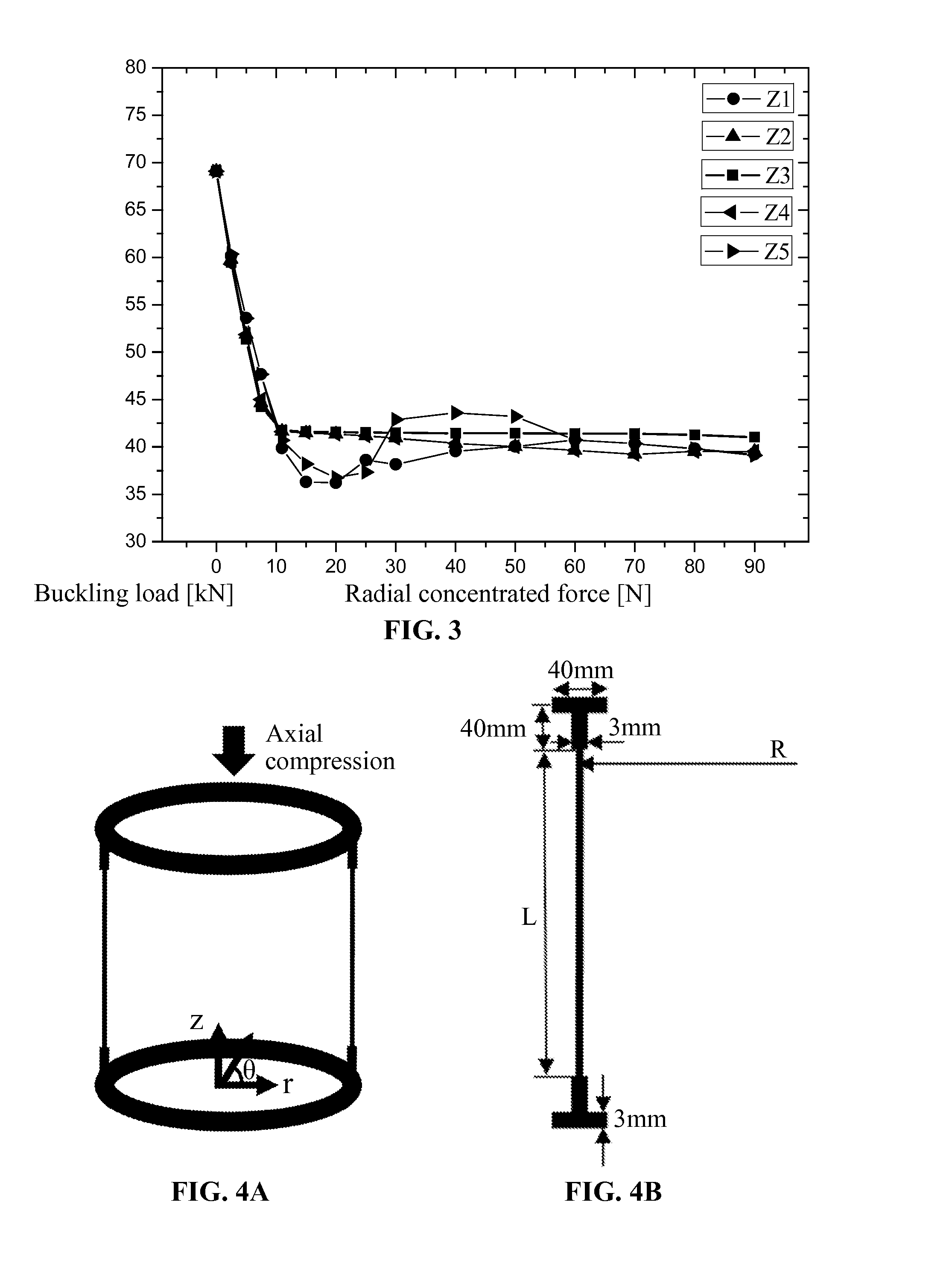
[0052]As shown in FIG. 4, a radius of the metal cylindrical shell R=250 mm, a length L=510 mm, a thickness t=0.5 mm. Material properties of 2024 aluminum alloy are as follows: elastic modulus E=72 GPa, Poisson's ratio ν=0.31, yield stress σs=363 MPa, ultimate stress σb=463 MPa, and density ρ=2.8E−6 kg / mm3. For the convenience of fixing and loading, T-rings are attached to both the bottom end and top end of the cylindrical shell, and made by the same material as the cylindrical shell. The bottom end of the T-rings is entirely clamped and the top end of the T-rings is constrained except for axial translational displacement.

[0053]As shown in FIG. 5, initial imperfections are introduced to the positions that are evenly distributed along the axial direction, and thereby a curve of the perturbation load vs. the buckling load of the structure can be drawn. When the initial imperfection (1.5 mm) is 3 times as thick as the shell skin, the corresponding radial perturbation load Nmax is 30 N. ...

example 2

[0056]As shown in FIG. 10, a radius of a cylindrical shell made by composite materials R=250 mm, a length L=510 mm, a ply angle thereof is [45 / −45 / 45 / −45 / 45] and thickness of each layer t=0.1 mm. Material properties are as follows: E11=84.56 GPa, E22=6.86 GPa, G12=G13=4.9 GPa, G23=1.96 GPa, ν12=0.3, ρ=1.7E−6 kg / mm3. For the convenience of fixing and loading, T-rings which are made by 2024 aluminum alloy are attached to both the bottom end and top end of the cylindrical shell. Material properties of the 2024 aluminum alloy are as follows: elastic modulus E=72 GPa, Poisson's ratio ν=0.31, yield stress σs=363 MPa, ultimate stress σb=463 MPa, and density ρ=2.8E−6 kg / mm3. The bottom end of the T-rings is entirely clamped and the top end of the T-rings is constrained except for axial translational displacement.

[0057]As shown in FIG. 11, initial imperfections are introduced to the positions that are evenly distributed along the axial direction, and thereby a curve of the perturbation load ...

example 3

[0060]As shown in FIG. 16, a radius of the metal cylindrical shell R=300 mm, a length L=600 mm, a thickness t=0.5 mm. Material properties of the 2024 aluminum alloy are as follows: elastic modulus E=72 GPa, Poisson's ratio ν=0.31, yield stress σs=363 MPa, ultimate stress σb=463 MPa, and density ρ=2.8E−6 kg / mm3. For the convenience of fixing and loading, T-rings are attached to both the bottom end and top end of the cylindrical shell, and made by the same material as the cylindrical shell. The bottom end of the T-rings is entirely clamped and the top end of the T-rings is constrained except for axial translational displacement.

[0061]As shown in FIG. 17, initial imperfections are introduced to the positions that are evenly distributed along the axial direction, and thereby a curve of the perturbation load vs. the buckling load of the structure can be drawn, as shown in FIG. 18. Assuming that the initial imperfection (1.5 mm) is 3 times as thick as the shell skin, the corresponding rad...


PUM


Abstract

A method for determining a reduction factor of a bearing capacity of an axial load cylindrical shell structure relates to stability checking of main bearing strength thin-walled members of aerospace and architectural structures. Different from experiment experience-based conventional defect sensitivity evaluating method represented by NASA SP-8007, a depression defect is introduced in a manner of applying a radial disturbance load. First, an influence rule of a depression defect amplitude of a single point to an axial load bearing capacity is analyzed by using numerical values, so as to determine a load amplitude range; then, defect sensitivity analysis is performed on depression defects of multiple points; then, experiment design sampling is performed by using load amplitude values and load position distribution as design variables; and finally, based on optimizing technologies such as an enumeration method, a genetic algorithm and a surrogate model, the most disadvantageous disturbance load of the multiple points that limits the defect amplitude is searched for, and a reduction factor of the bearing capacity of the axial load cylindrical shell structure is determined, so as to establish a more physical method for evaluating the defect sensitivity and the bearing performance of the axial load cylindrical shell structure.

Description

CROSS-REFERENCE TO RELATED APPLICATIONS[0001]This application is a National Stage Appl. filed under 35 USC 371 of International Patent Application No. PCT / CN2014 / 000152 with an international filing date of Feb. 12, 2014, designating the United States, now pending, and further claims priority benefits to Chinese Patent Application No. 201310113723.8 filed Apr. 3, 2013. The contents of all of the aforementioned applications, including any intervening amendments thereto, are incorporated herein by reference.FIELD OF THE INVENTION[0002]The invention relates to stability analysis with respect to the thin-walled components carrying main load in aerospace or architectural structures, and more particularly to a method for determining a knockdown factor of load-carrying capacity of a cylindrical shell subjected to axial compression.BACKGROUND OF THE INVENTION[0003]A rocket body bears huge takeoff thrust in the launching phase, and thus the axial compressive load is the most important conside...

Claims


Application Information

Patent Timeline
Patent Type & Authority Applications(United States)
IPC IPC(8): G01M99/00
CPCG01M99/007B64C1/068G06F2113/28G06F2111/10G06F30/23Y02T90/00
Inventor WANG, BOHAO, PENGLI, GANGTIAN, KUOMENG, ZENGDU, KAIFANZHOU, YANZHANG, XITANG, XIAOHANWANG, BINLUO, HONGZHI
Owner DALIAN UNIV OF TECH
Why Eureka
Try Eureka