Cleaning Assembly for a Harvester

a technology of cleaning assembly and harvester, which is applied in the direction of cleaning process and apparatus, solid separation, agriculture tools and machines, etc., can solve the problems of insufficient air directed to the rear, insufficient air in front and in the rear, and insufficient air at the rear, so as to achieve efficient use of the available surface for sieve activity, efficient airflow, and minimal grain loss

Active Publication Date: 2016-07-07
BLUE LEAF I P INC +1
View PDF12 Cites 12 Cited by
  • Summary
  • Abstract
  • Description
  • Claims
  • Application Information

AI Technical Summary

Benefits of technology

[0010]The invention thus seeks to provide a cleaning assembly for a harvester having a well-balanced air distribution, having an efficient airflow and at the same time having a minimal grain loss.SUMMARY OF THE INVENTION

Problems solved by technology

The disadvantage thereof is that air is directed to the rear, but not sufficient relative to the huge length.
There is too much air in front and not enough at the rear.
Consequently, no efficient use of the available surface for sieve activity is obtained.
This however is a very unstable cleaning, hard to adjust, with a bad grain sample as a consequence.
The problem with this cleaning shoe arrangement however is that clean grain from the receiving element that is falling onto the grain pan and that is guided by means of the deflector surfaces towards the clean grain auger, being the major part of the cleaned grain, falls in front of the main duct of the blower.
This reduces the efficiency of the airflow and increases grain loss.

Method used


Image

  • Cleaning Assembly for a Harvester
  • Cleaning Assembly for a Harvester
  • Cleaning Assembly for a Harvester

Examples


Embodiment Construction

)

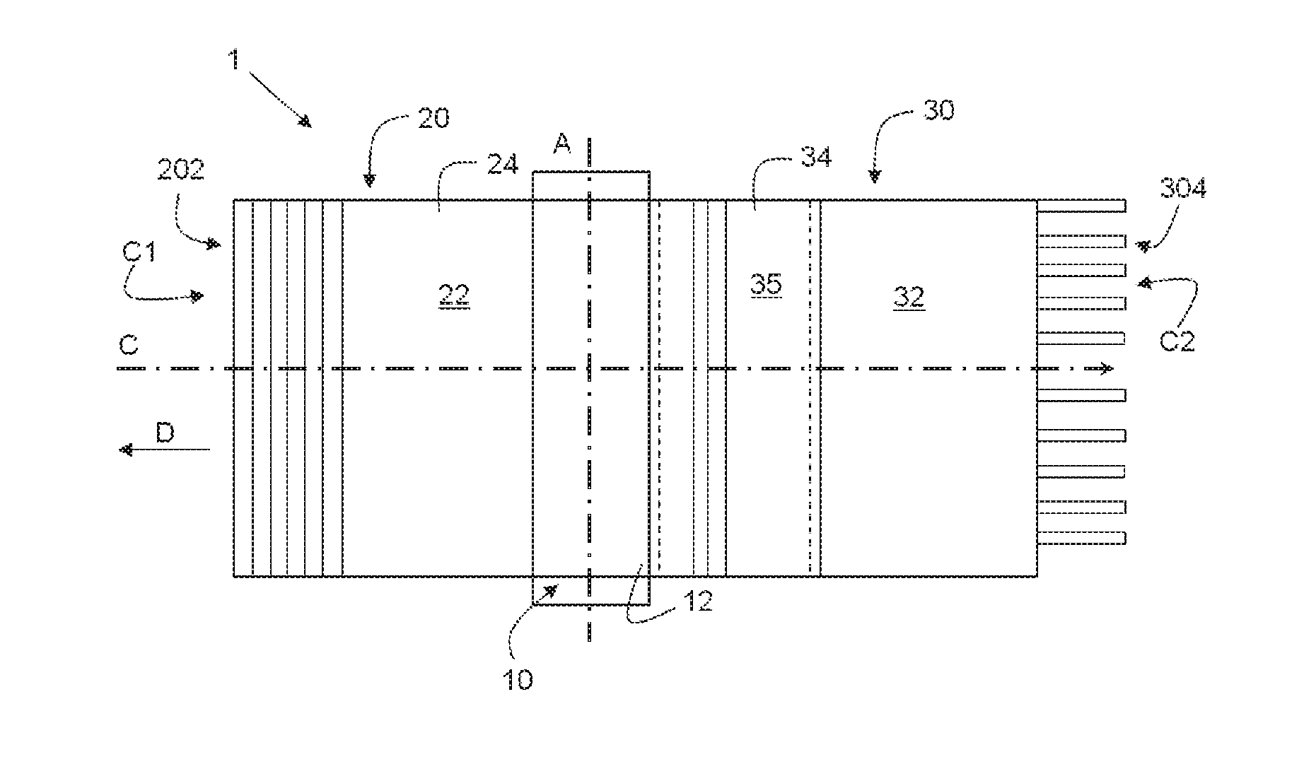
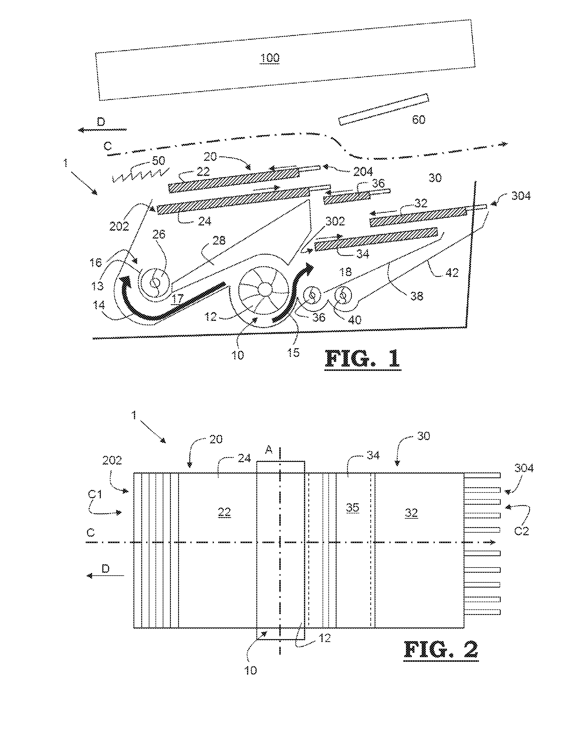
[0049]A cleaning assembly (1) according to the invention for a harvester operable to clean crop (not shown on the figures) while moving along a direction of the crop flow (C) from an upstream entrance (C1) to a downstream exit (C2), as shown in FIGS. 1 and 2, comprises firstly a fan assembly (10). This direction of the crop flow (C) is opposite to the driving direction (D) of the harvester.

[0050]This fan assembly (10) comprises a fan (12) (also called blower) that is operable to rotate about a rotation axis (A) (see FIG. 2) transverse to the direction of the crop flow (C) for generating an air flow. The fan assembly (10) comprises a first fan outlet (16) and a second fan outlet (18) operable to output the flow of air (14, 15) generated by the fan (12). The first fan outlet (16) is arranged at an upstream side of the rotational axis (A) and the second fan outlet (18) is arranged at a downstream side of the rotational axis (A).

[0051]The cleaning assembly (1) according to the inventio...


PUM


Abstract

A cleaning assembly for a harvester has a fan assembly with a fan and a first fan outlet and a second fan outlet, a first sieve assembly with at least one reciprocable sieve, an upstream end of the first sieve assembly near the first fan outlet such that air from the first fan outlet flows along the first sieve assembly and a direction of crop flow; and a second sieve assembly has at least one reciprocable sieve, an upstream stream end of the second sieve assembly near the second fan outlet such that the air from the second fan outlet flows along the second sieve assembly and the direction of crop flow, the second sieve assembly has a clean grain auger for receiving cleaned grain, and the first sieve assembly has a further clean grain auger arranged for receiving cleaned grain.

Description

[0001]This application is the US National Stage filing of International Application Serial No. PCT / EP2014 / 064925 filed on Jul. 11, 2014 which claims priority to Belgian Application BE2013 / 0486 filed Jul. 12, 2013, each of which is incorporated herein by reference in its entirety.FIELD OF THE INVENTION[0002]The present invention generally relates to a cleaning assembly for a harvester, such as a combine harvester, operable to clean a crop, while moving along a direction of the crop flow from an upstream entrance to a downstream exit.BACKGROUND OF THE INVENTION[0003]In a combine harvester, after a crop has been cut, it is passed through a thresher which acts to separate the grain from the stalks or the straw. The straw is transported to the back of the harvester by means of straw walkers, while the grain and other crop particles are dropped onto one or more sieves. The material other than grain (hereafter further abbreviated with “MOG”) comprises chaff, short straw and other particles...

Claims


Application Information

Patent Timeline
Patent Type & Authority Applications(United States)
IPC IPC(8): A01F12/44A01F12/46
CPCA01F12/444A01F12/46A01F12/446A01F12/448
Inventor MISSOTTEN, BART M. A.DUQUESNE, FRANK R.G.SOMERS, TOM N. N.
Owner BLUE LEAF I P INC
Why Eureka
Try Eureka