Blood flow control system and methods for in-vivo imaging and other applications

a control system and flow control technology, applied in the field of in-vivo imaging and other applications, can solve problems such as affecting the potential diagnostic performance and quality of the entire investigation, and achieve the effects of improving and standardized flow accuracy, enhancing blood flow control, and enhancing properties

Active Publication Date: 2016-07-07
GUTZEIT ANDREAS
View PDF0 Cites 1 Cited by
  • Summary
  • Abstract
  • Description
  • Claims
  • Application Information

AI Technical Summary

Benefits of technology

[0008]In the view of the above it is seen as an object of the invention to provide a specific dedicated device and its use, a scanning system and methods with improved and standardized flow accuracy and enhancement in the control of blood flow, dilution and enhancement properties for imaging of contrast enhanced blood flow (perfusion, first-pass enhancement, vascular supply of tumors, lesions and various tissues), particularly in relation to the vascular flow (perfusion, fist-pass enhancement, arterial enhancement, improved detection of thromboembolic material within blood vessels, vascular space and supply of lesions, tumors and normal tissue) through the pulmonary artery or other arteries and veins as well as other vessels distally to the heart.
[0021]The methods, the devices and systems and their use are in particular able to control and standardize blood flow to perform high contrast density within arteries and / or veins, such as pulmonary vessels, brain vessels, vessels of visceral organs or vessels of the extremities or other vessels within a human or animal body. Standardized blood flow increases contrast density in the above vessels, increasing image quality of images taken with imaging systems such as mentioned. On the other hand the methods, devices and systems and their use may allow to reduce the amount of contrast substances.

Problems solved by technology

This dilution influences potentially the diagnostic performance and quality of the entire investigation.

Method used


Image

  • Blood flow control system and methods for in-vivo imaging and other applications
  • Blood flow control system and methods for in-vivo imaging and other applications
  • Blood flow control system and methods for in-vivo imaging and other applications

Examples


Embodiment Construction

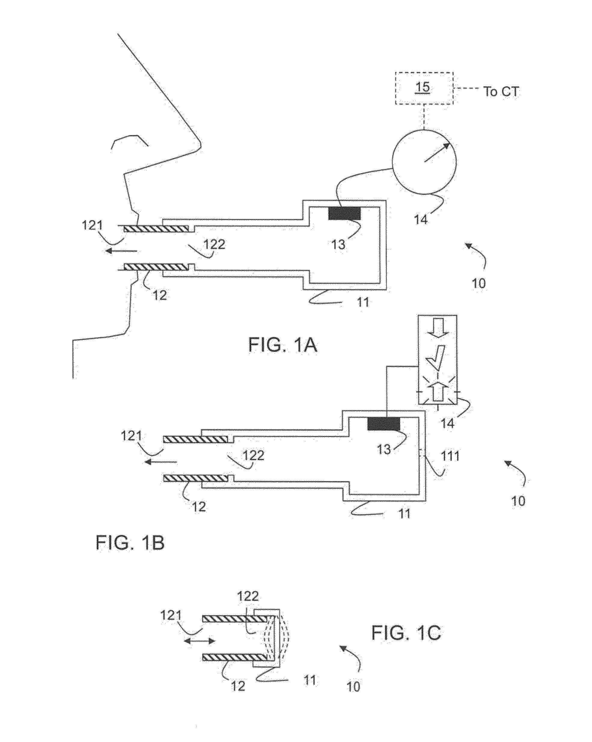
[0029]An exemplary respiratory resistance device 10 is shown in FIG. 1A. The device has a main body 11 of resilient material such as Teflon® or stainless steel or other similar materials. The main body provides a cap and holder for a disposable mouthpiece 12. The mouth piece and the main body are connected to each other by a simple form fitting attachment so that the mouth piece can be easily attached and removed from the main body by a straight insertion and extraction movement, preferably without involving a twist or use of a tool. Any similar form or attachment method might be suitable.

[0030]The mouth piece 12 has an essentially tubular, hollow shape with a proximate opening 121 adapted for insertion into a patient's mouth and a distal opening 122 providing a flow connection into the interior of the main body 11.

[0031]It should be however clear that materials, dimensions and shapes of the main body 11 and the mouthpiece can vary widely while still maintaining the function of prov...


PUM


Abstract

A method of and device for acquiring in-vivo images or quantitative / qualitative data (perfusion, blood flow, vascularization, contrast enhancement, selective blood supply management) of interior parts of the human body (20) is described, using an imaging system (21) and including the steps of positioning the body (20) relatively to the imaging system (21), applying a respiratory resistance device (10) to the respiratory system of the body (20), and performing an image acquisition step during or concomitantly an inhalation / inspiration / suction or exhalation / Valsalva / expiration phase, during which the body provides suction or exhalation against a resistance as provided by the respiratory resistance device (10).

Description

FIELD OF THE INVENTION[0001]The present invention relates to blood flow control systems, devices and methods, in particular to an imaging system for the human body, such as x-ray and related tomographic imaging systems.BACKGROUND OF THE INVENTION[0002]Images of the interior of the human body are a long-established tool for providing graphic information in form of pictures, prints and screen displays for a subsequent interpretation by skilled practitioners.[0003]For many purposes detection of blood flow related conditions is an important part of such images. In order to improve the detection of blood flow conditions it is known that injection of a contrast medium into the blood stream can add information.[0004]A well-known example of such methods is computer tomography (CT) angiography, which is widely accepted as standard method for the examination of patients with suspected pulmonary embolism and other vascular and parenchymal diseases. The advantages of CT are obvious: it is widel...

Claims


Application Information

Patent Timeline
Patent Type & Authority Applications(United States)
IPC IPC(8): A61B6/00A61B6/03A61B8/08A61B8/06
CPCA61B6/507A61B8/06A61B8/481A61B6/504A61B6/032A61B6/481A61B5/055A61B5/08G01R33/5601A63B23/18G01R33/563G01R33/56509A63B23/185A63B21/0088
Inventor GUTZEIT, ANDREAS
Owner GUTZEIT ANDREAS
Why Eureka
Try Eureka