
Workpiece processing chamber having a rotary microwave plasma antenna with slotted spiral waveguide

a processing chamber and spiral waveguide technology, applied in the field of chambers or reactors, can solve the problems of short deposition time, inability to meet the stringent uniformity required of microwave sources, and increased density

Active Publication Date: 2016-07-07
APPLIED MATERIALS INC
View PDF0 Cites 9 Cited by
  • Summary
  • Abstract
  • Description
  • Claims
  • Application Information

AI Technical Summary

Benefits of technology

The patent describes a reactor for processing workpieces using microwave technology. The reactor includes a chamber with a workpiece support surface and a rotary coupling. The microwave source is connected to the chamber through an axial conduit and a distributor waveguide. The distributor waveguide has multiple ports and reflective surfaces to deflect and distribute the microwave energy. The reactor can be used in various ways to process workpieces, such as by placing the microwave antenna over the workpiece processing chamber or by aligning the microwave source and rotary coupling with the chamber. The technical effects of the invention include improved processing efficiency and uniformity, as well as improved control over the distribution of microwave energy.

Problems solved by technology

A higher plasma density requires higher source power and generally translates to a shorter deposition time.
However, a microwave source cannot meet the stringent uniformity required for distribution across the workpiece of deposition rate or etch rate.
The antenna has a periodic power deposition pattern reflecting the wave pattern of the microwave emission and the slot layout, rendering the process rate distribution non-uniform.
This prevents attainment of the desired process rate uniformity across the workpiece.
A limitation on processing rate is the amount of microwave power that can be delivered to a process chamber without damaging or overheating the microwave window of the chamber.
The microwave window provides a vacuum boundary of the chamber and is consequently subject to significant mechanical stress, rendering it vulnerable to damage from overheating.

Method used


Image

  • Workpiece processing chamber having a rotary microwave plasma antenna with slotted spiral waveguide
  • Workpiece processing chamber having a rotary microwave plasma antenna with slotted spiral waveguide
  • Workpiece processing chamber having a rotary microwave plasma antenna with slotted spiral waveguide

Examples


Embodiment Construction

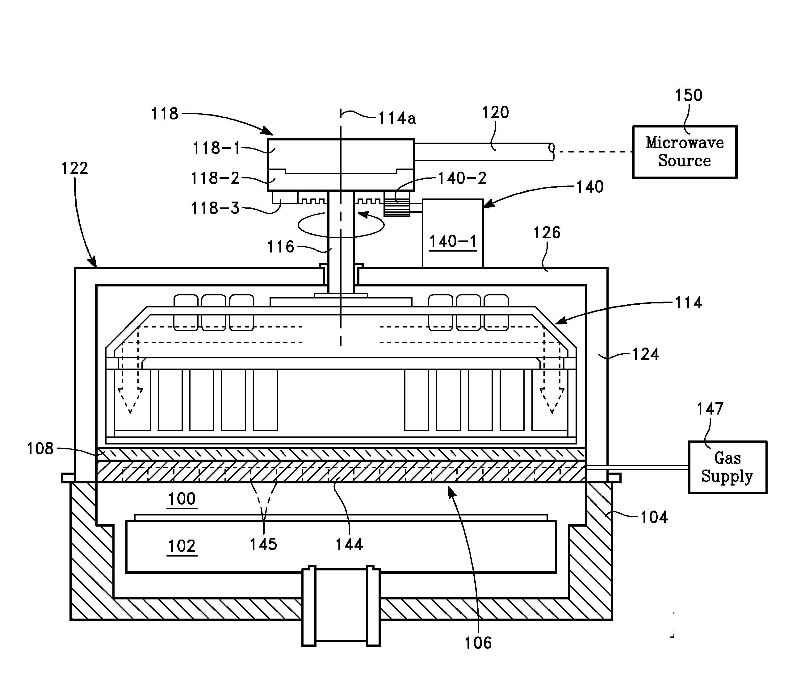
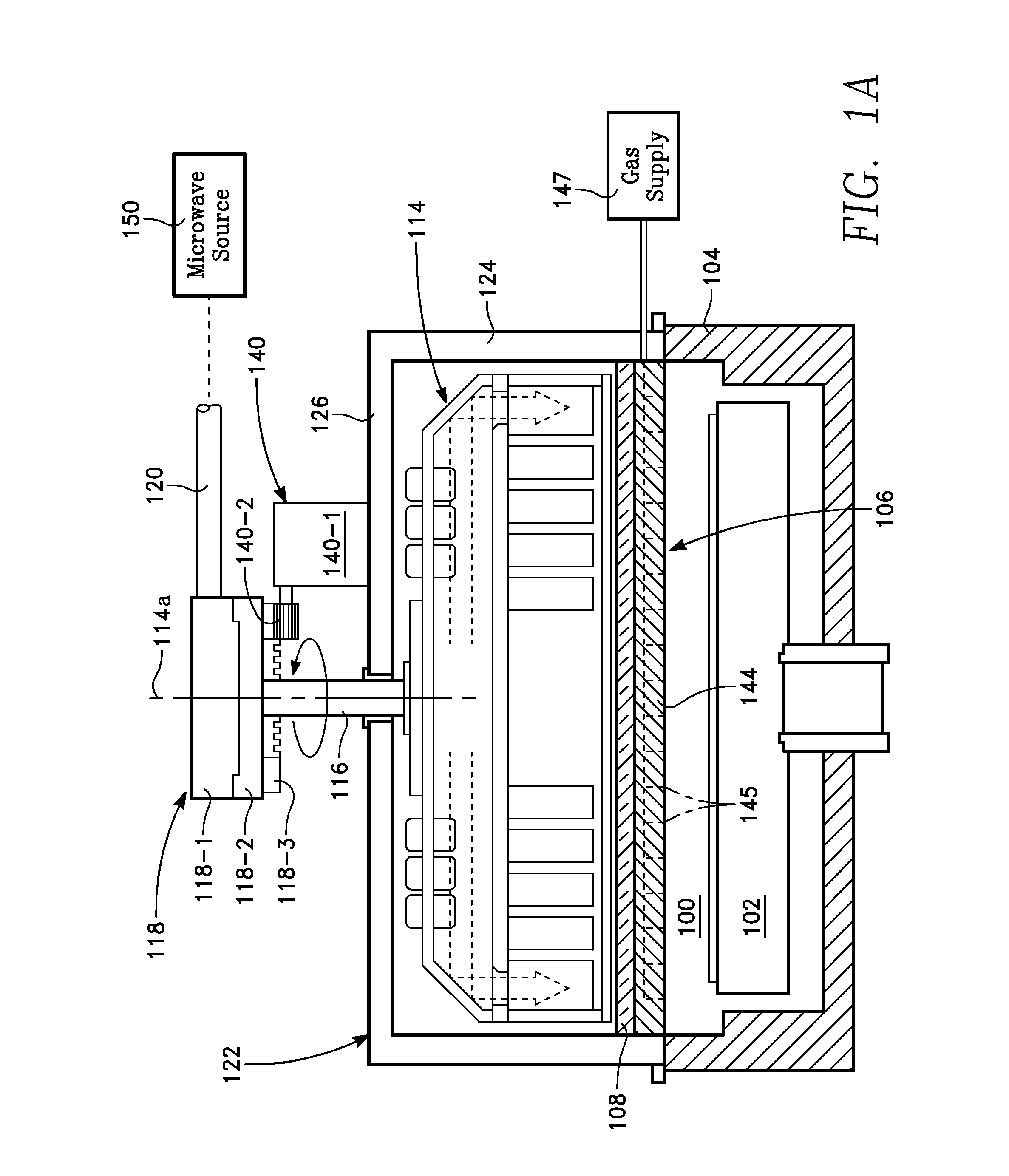
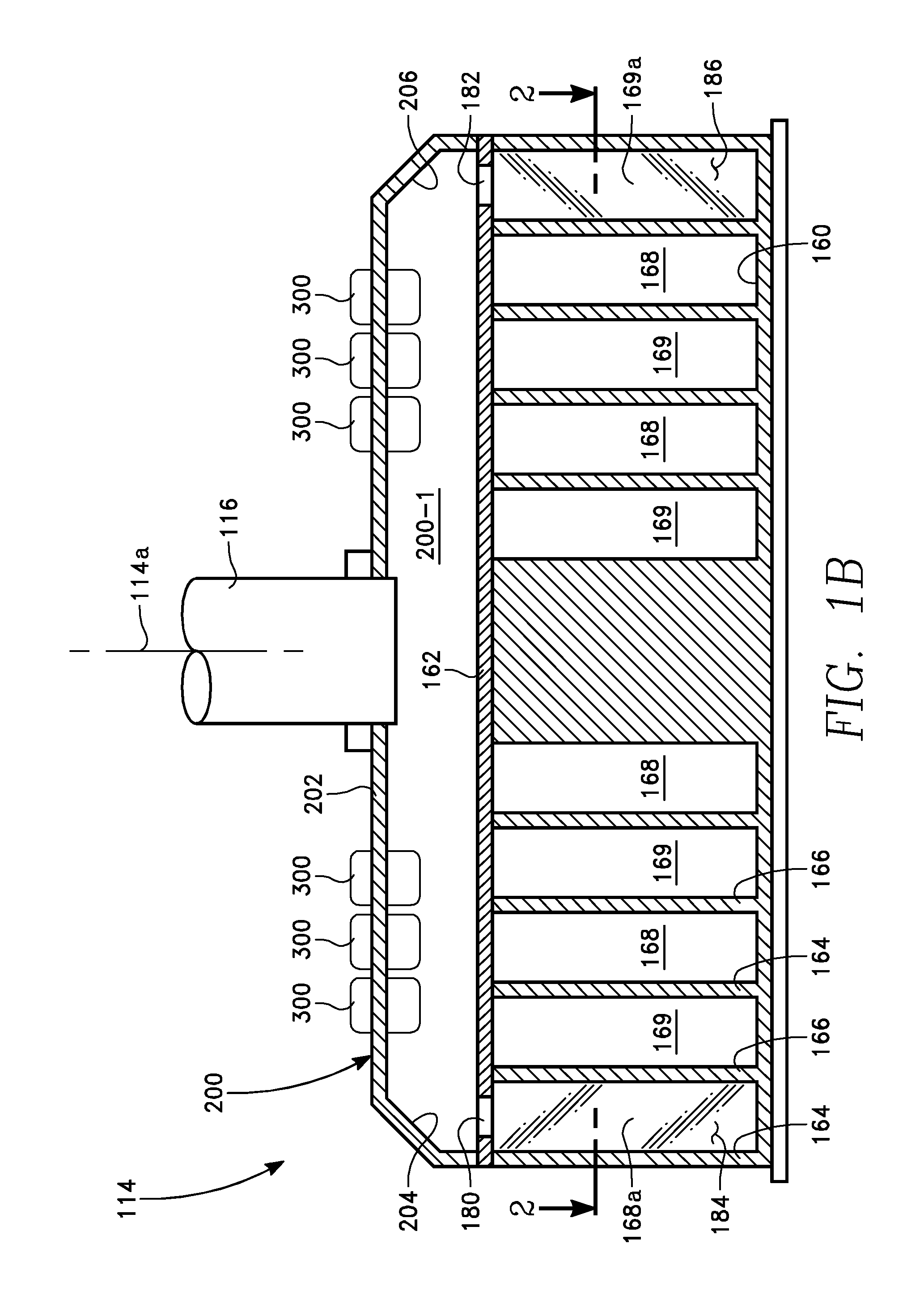
[0030]Referring now to FIGS. 1A and 1B, a workpiece processing reactor includes a chamber 100 containing a workpiece support 102. The chamber 100 is enclosed by a side wall 104 and a ceiling 106 formed of a microwave transparent material such as a dielectric material. In one embodiment, the ceiling 106 may be implemented as a dielectric window 108 formed in the shape of a disk. A rotating microwave antenna 114 overlies the dielectric window 108. The microwave antenna 114 is enclosed by a conductive shield 122 consisting of a cylindrical side wall 124 and a disk-shaped cap 126. In one embodiment depicted in FIG. 2, the microwave antenna 114 is disk-shaped.

[0031]As shown in FIG. 1A, the microwave antenna 114 is fed by an axial waveguide 116. The axial waveguide 116 is coupled through an overlying rotary microwave coupling 118 to a stationary microwave feed 120. The rotary coupling 118 includes a stationary member 118-1 and a rotatable member 118-2. The stationary member 118-1 is stati...


PUM

PropertyMeasurementUnit
diameteraaaaaaaaaa
angleaaaaaaaaaa
angleaaaaaaaaaa

Abstract

A microwave antenna includes a first spiral conduit having a first conduit end, first plural ports in a floor of the first spiral conduit spaced apart along the length of the first spiral conduit; an axial conduit coupled to a rotatable stage; and a distributor waveguide comprising an input coupled to the axial conduit and a first output coupled to the first conduit end.

Description

CROSS-REFERENCE TO RELATED APPLICATIONS[0001]This application claims benefit of U.S. Provisional Application Ser. No. 62 / 100,595, filed Jan. 7, 2015 entitled WORKPIECE PROCESSING CHAMBER HAVING A ROTARY MICROWAVE PLASMA ANTENNA WITH SLOTTED SPIRAL WAVEGUIDE, by Michael W. Stowell.BACKGROUND[0002]1. Technical Field[0003]The disclosure concerns a chamber or reactor for processing a workpiece such as a semiconductor wafer using microwave power.[0004]2. Description of Related Art[0005]Processing of a workpiece such as a semiconductor wafer can be carried out using a form of electromagnetic energy, such as RF power or microwave power, for example. The power may be employed, for example, to generate a plasma, for carrying out a plasma-based process such as plasma enhanced chemical vapor deposition (PECVD) or plasma enhanced reactive ion etching (PERIE). Some processes need extremely high plasma ion densities with extremely low plasma ion energies. This is true for processes such as deposi...

Claims


Application Information

Patent Timeline
Patent Type & Authority Applications(United States)
IPC IPC(8): H01J37/32H01Q13/00
CPCH01J37/3222H01Q13/00H01J2237/3321H01J2237/327H01J2237/3341H01J37/32229H01J37/32192H01J2237/32H01Q13/22
Inventor STOWELL, MICHAEL W.
Owner APPLIED MATERIALS INC
Learn More