Dual return activated sludge process in a flow-equalized wastewater treatment system

a wastewater treatment system and flow-equalization technology, applied in biological water/sewage treatment, biological sludge treatment, sustainable biological treatment, etc., can solve the problems of significant challenges in industrial wastewater treatment or municipal treatmen

Active Publication Date: 2016-07-14
REID JOHN H
View PDF1 Cites 9 Cited by
  • Summary
  • Abstract
  • Description
  • Claims
  • Application Information

AI Technical Summary

Benefits of technology

[0006]Disclosed herein is a process for operating a two-stage activated sludge wastewater or sewage treatment system in which a dual RAS flow is provided such that a first RAS flow is conducted from a common downstream final clarifier to the first AS stage with a low flow rate and a second RAS flow is conducted from the final clarifier to the second AS stage with a high flow rate.

Problems solved by technology

Significant challenges remain in the treatment of industrial wastewater or municipal sewage based on the variability of pollutant concentrations, volume, and temperature of the influent into a treatment facility.

Method used


Image

  • Dual return activated sludge process in a flow-equalized wastewater treatment system
  • Dual return activated sludge process in a flow-equalized wastewater treatment system
  • Dual return activated sludge process in a flow-equalized wastewater treatment system

Examples


Embodiment Construction

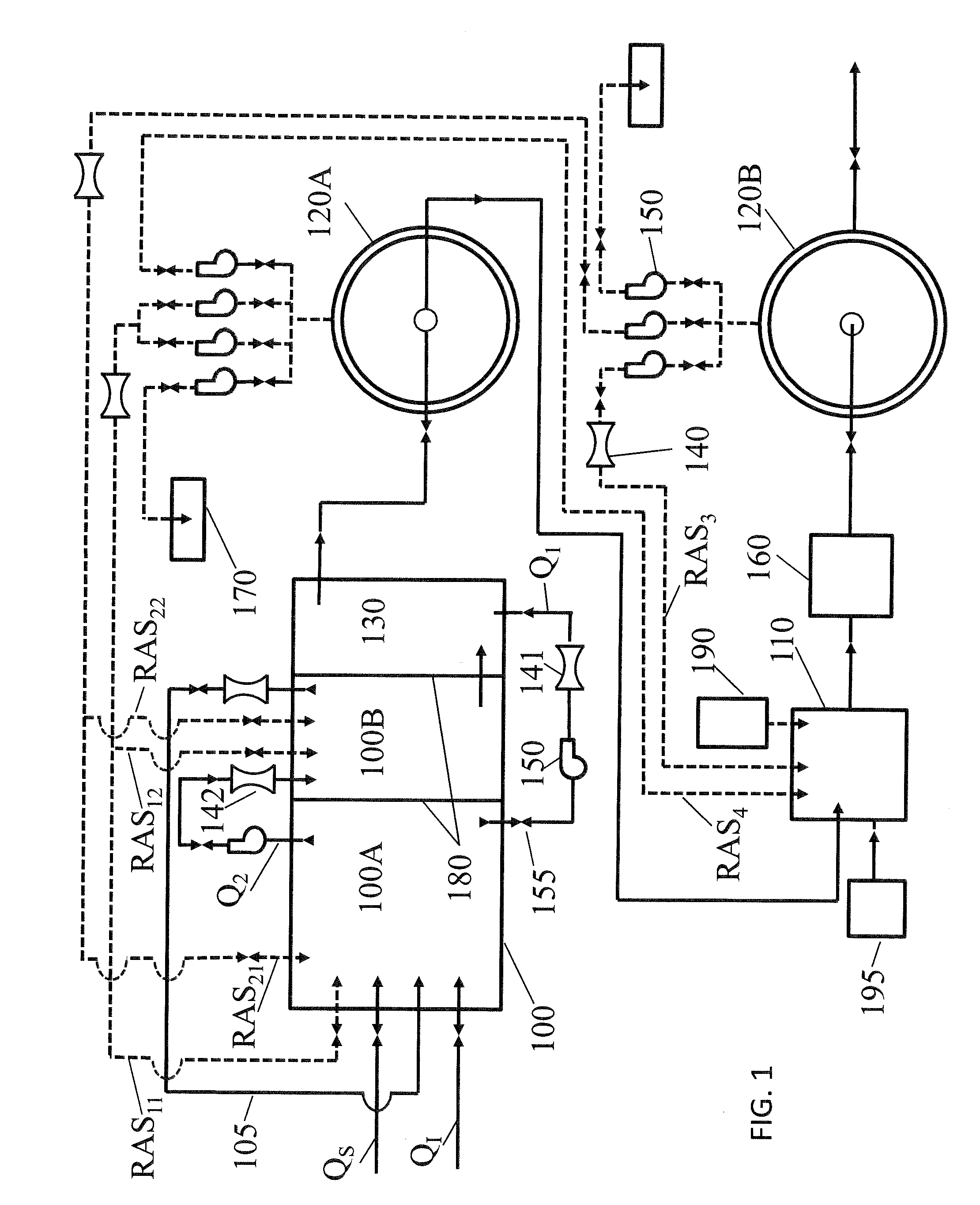
[0014]The foregoing and other objects, aspects, and advantages of the disclosure will be better understood from the following detailed description of the best and various embodiments. Throughout the various views and illustrative embodiments of the present disclosure, like reference numbers are used to designate like elements.

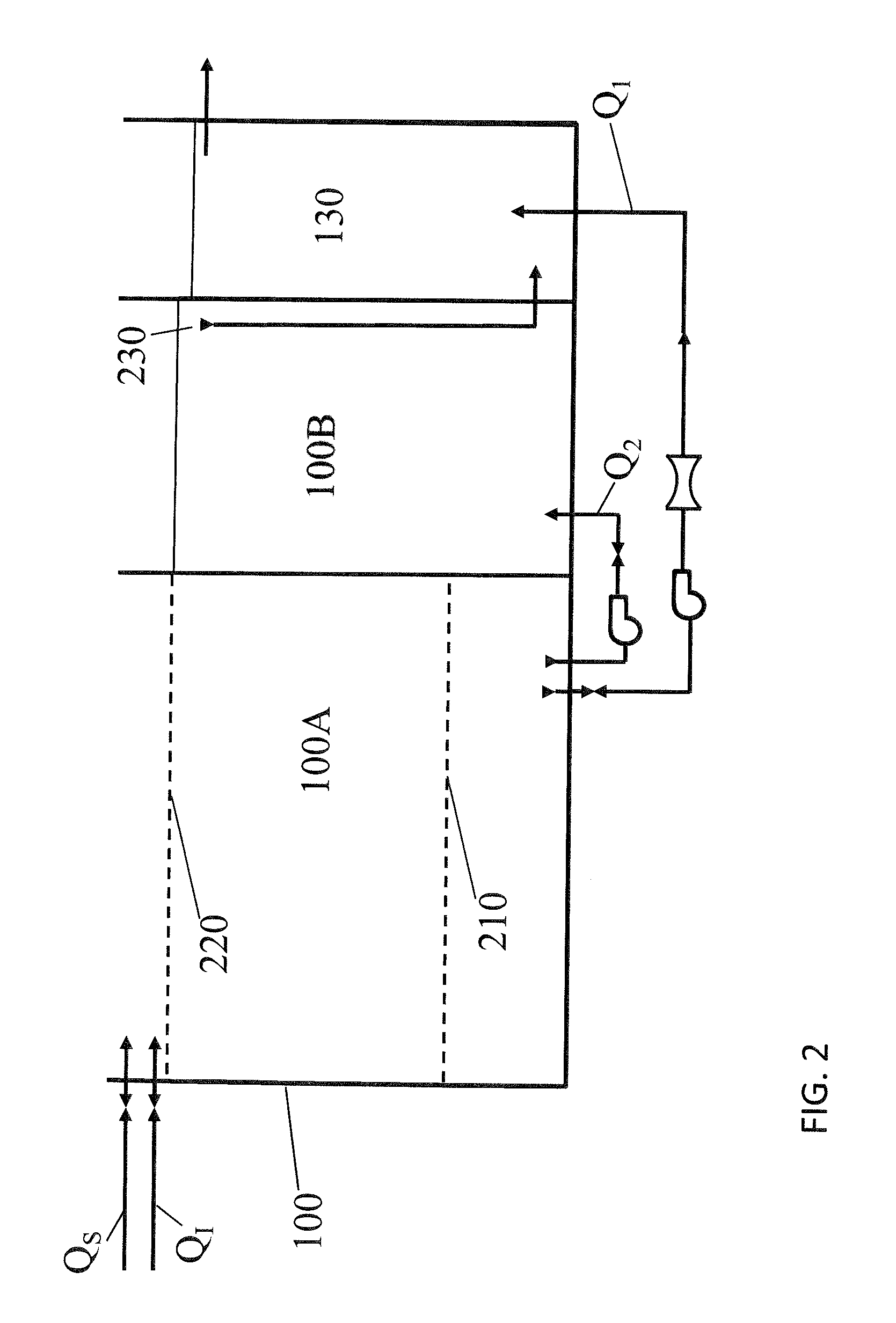
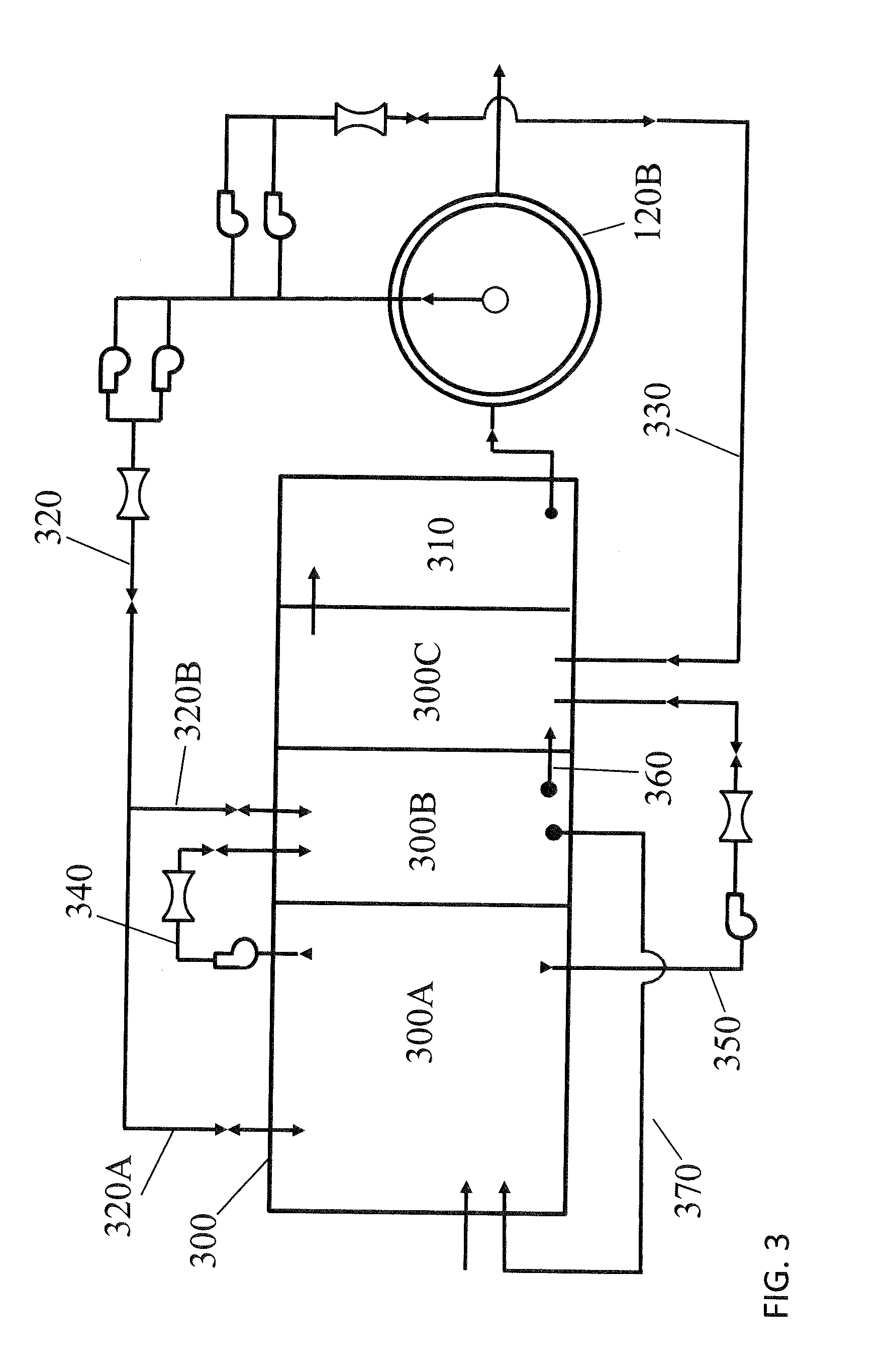
[0015]In a typical embodiment, the mixed liquor flow from the anammox reactor is received in a plurality of clarifiers that are operated in parallel. Throughout this disclosure, a plurality means two or more.

[0016]In another typical embodiment, the bypass flow from the flow equalization reactor and the outflow from the nitritation reactor are blended in the anammox reactor. In yet another typical embodiment, the mean cell residence time (MCRT) of the flow equalization reactor, the nitritation reactor or the equalization reactor and the nitritation reactor is adjusted to be of from 2 to 5 days.

[0017]In a particular embodiment, the MCRT of the anammox reactor is ...


PUM

PropertyMeasurementUnit
mean cell residence timeaaaaaaaaaa
concentrationaaaaaaaaaa

Abstract

A common final clarifier is provided downstream of a two-stage activated sludge (AS) system that includes a flow equalization basin (FEB) reactor and a nitritation reactor as the first AS stage and an anammox reactor as the second AS stage. A first return activated sludge (RAS) flow is conducted from the final clarifier to the first AS stage with a low flow rate and a second segregated RAS flow is conducted to the second AS stage with a high flow rate. The FEB reactor is operated as an anoxic reactor to achieve carbonaceous BOD removal; conversion of organic nitrogen to ammonia nitrogen; and, denitrification of recycled nitrite or nitrate nitrogen. The nitritation reactor is operated as an aerobic reactor to achieve oxidation of ammonia nitrogen to nitrite nitrogen by biological nitritation. The anammox reactor is operated at zero or very low dissolved oxygen concentration to achieve nitrogen removal by deammonification.

Description

CROSS REFERENCE TO RELATED APPLICATION[0001]This application is a continuation-in-part of U.S. patent application Ser. No. 14 / 593,508, filed Jan. 9, 2015, the entire content of which is incorporated herein by reference.FIELD OF THE DISCLOSURE[0002]A two-stage activated sludge (AS) wastewater treatment system is disclosed in which the first stage includes a flow equalization basin (FEB) reactor and a nitritation reactor and the second stage includes an anammox reactor. The FEB reactor provides flow equalization of the wastewater or sewage influent. A common final clarifier is arranged downstream of the second AS stage.BACKGROUND[0003]It is known from US2013 / 0327710 to mix the outflow of sequential treatment zones in an anaerobic lagoon or tank design to achieve improved carbon to nitrogen ratio control of the effluent. The anaerobic lagoon or tank produces a blended wastewater or sewage mixture with an adequately high carbon to nitrogen ratio for a downstream activated sludge treatme...

Claims


Application Information

Patent Timeline
Patent Type & Authority Applications(United States)
IPC IPC(8): C02F11/04
CPCC02F11/04C02F3/22C02F3/303C02F3/307C02F2209/10C02F2209/40C02F2301/043Y02W10/10
Inventor REID, JOHN H.
Owner REID JOHN H
Why Eureka
Try Eureka