Phase control loop, generator control device and method for activating an electric drive system of a hybrid vehicle

a hybrid vehicle and generator control technology, applied in the direction of electric generator control, electric motor propulsion transmission, locomotive transmission, etc., can solve the problem of increasing the torque ripple of the drive shaft, and achieve the effect of preventing torque vibration, reducing the number of back-feeding vibrations, and improving the nvh (“noise, vibration, harness”) of the engin

Active Publication Date: 2016-07-14
ROBERT BOSCH GMBH
View PDF5 Cites 2 Cited by
  • Summary
  • Abstract
  • Description
  • Claims
  • Application Information

AI Technical Summary

Benefits of technology

[0010]A concept of the present invention is to compensate the torque surges generated in a pulsating manner in the internal combustion engine and the periodic torque ripple which occurs on the drive shaft of an electric generator by means of a corresponding correction signal for the rotational speed regulation of the generator. This takes place via a phase control loop (PLL, “phase-locked loop”) which removes a subtraction of the ignition synchronous vibrations from the rotational speed control signal. As a result, the rotational speed controller of the generator control device no longer reacts to the torque ripple generated by the internal combustion engine and thus prevents torque vibrations at the drive shaft and simultaneously fluctuations in the current generation by the generator.
[0011]A significant advantage of this procedural approach is that vibrations which are fed back can be reduced to the housing of the internal combustion engine. Particularly in the case of internal combustion engines with low flyweights, this improves the NVH (“noise, vibration, harness”) of the engine and consequently contributes to an extended service life of the engine components due to reduced mechanical wear on said components.
[0012]In addition, there is the advantage that current oscillations or current ripples can also be reduced in the current produced by the generator. Because the power loss in a battery increases quadratically with the amperage and proportionally to the battery internal resistance, the efficiency of the traction battery being supplied with current as well as the service life thereof can increase as a result of reduced heat input.
[0013]Finally, the use of a phase control loop vis-à-vis alternative methods, such as the use of notch filters for filtering the ignition frequencies, has the advantage that the control dynamics are not impaired, particularly because the phase control loop in contrast to notch filters does not have a shift in the phase response and therefore the phase reserve is not negatively impacted.
[0014]According to one embodiment of the phase control loop according to the invention, the phase control loop can furthermore have a harmonic generator, which is coupled to the input connection and which is designed to generate harmonic signals of the measured rotational speed signal and to output said harmonic signals as an input signal to the correction function device, wherein the correction function device is designed furthermore to determine the rotational speed correction signal on the basis of the harmonic signals. This particularly facilitates a correction of the torque on the drive shaft which is as accurate as possible, particularly in the case of asymmetrical torque pulsations. According to a further embodiment of the phase control loop according to the invention, the harmonic generator can be designed to generate harmonic signals up to at least the second harmonic. As a result, rotational speed ripples are simulated with adequate accuracy with a reasonable amount of computing time and effort.

Problems solved by technology

This reduction of the flyweight, however, simultaneously causes an increase in the torque ripple of the drive shaft by means of the torque of the engine pulsating at the ignition frequency of the internal combustion engine.

Method used


Image

  • Phase control loop, generator control device and method for activating an electric drive system of a hybrid vehicle
  • Phase control loop, generator control device and method for activating an electric drive system of a hybrid vehicle
  • Phase control loop, generator control device and method for activating an electric drive system of a hybrid vehicle

Examples


Embodiment Construction

[0023]Identical reference signs generally denote similar or similarly functioning components. The schematic geometric models shown in the figures are only of an exemplary nature and are illustrated in an ideal manner for the sake of clarity. It goes without saying that in practice geometric models which deviate from these models due to boundary conditions that deviate therefrom can result, and that the geometric models depicted are only used to illustrate principles and functional aspects of the present invention.

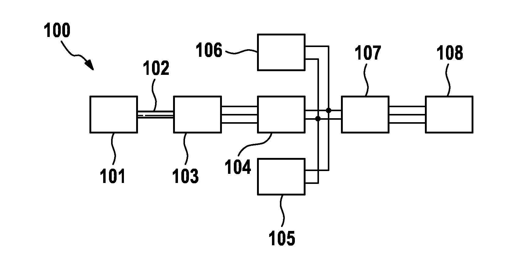
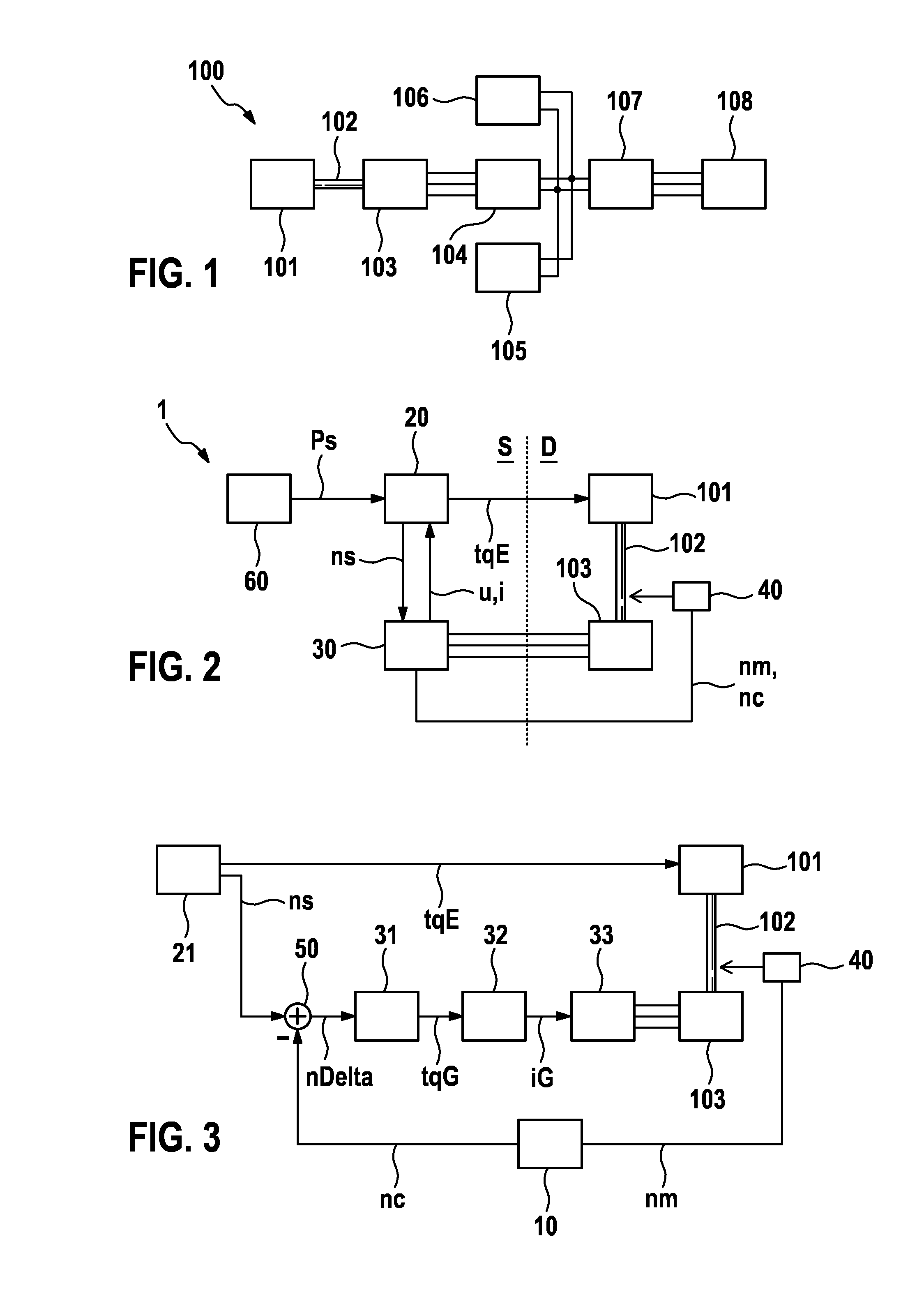
[0024]FIG. 1 shows a schematic depiction of a drive train 100 for a serially coupled hybrid vehicle. The drive train 100 comprises an internal combustion engine 101, which, by way of example, is connected to an electric generator 103 via a drive shaft 102. Alternatively to a drive shaft 102, the internal combustion engine 101 and the generator 103 can also be connected to each other by means of a belt or a gearing mechanism. For example, the internal combustion engine 101 c...


PUM


Abstract

The invention relates to a phase control loop for the rotational speed regulation of an electric generator fed by an internal combustion engine, having an input connection, which is designed to receive a rotational speed signal measured on a drive shaft of the electric generator, an amplitude determination device, which is coupled to the input connection and which is designed to determine the amplitude of rotational speed ripples of the measured rotational speed signal, a correction function device, which is coupled to the amplitude determination device and the input connection and which is designed to determine a rotational speed correction signal on the basis of the determined amplitude of the rotational speed ripple and of the measure rotational speed signal, a phase discriminator, which is coupled to the amplitude determination device and the correction function device and which is designed to determine a phase difference signal between the measured rotational speed signal and the rotational speed correction signal, wherein the correction function device is designed to regulate the rotational speed correction signal on the basis of the determined phase difference signal to a phase difference of zero, and a summing element, which is designed to subtract the rotational speed correction signal from the measured rotational speed signal and to provide a corrected rotational speed signal to an output connection of the phase control loop.

Description

BACKGROUND OF THE INVENTION[0001]The invention relates to a phase control loop, a generator control device and a method for activating an electric drive system of a hybrid vehicle.[0002]An internal combustion engine drives an electrical machine as a generator in hybrid vehicles having range extenders. The internal combustion engine is thus permanently mechanically coupled to the generator. Because the internal combustion engine does not have to be driven with low rotational speeds, the flyweight of the internal combustion engine can be chosen small or completely saved, wherein only the mass of the internal combustion engine and the electrical machine is used as the flyweight. This reduction of the flyweight, however, simultaneously causes an increase in the torque ripple of the drive shaft by means of the torque of the engine pulsating at the ignition frequency of the internal combustion engine.[0003]The German patent publication DE 10 2004 062 012 A1 proposes, for example, in a sys...

Claims


Application Information

Patent Timeline
Patent Type & Authority Applications(United States)
IPC IPC(8): H02P9/04
CPCH02P9/04H02P21/05B60K6/46B60W10/06B60W20/00Y02T10/62
Inventor SPIELMANN, BERNDSILBERBAUER, MARTINPRAXMARER, MEINRADMEDVECKY, MILOS
Owner ROBERT BOSCH GMBH
Why Eureka
Try Eureka