Method for separating carbon dioxide from a gas flow, in particular from a flue gas flow, and separating device for separating carbon dioxide from a gas flow, in particular from a flue gas flow

a technology of carbon dioxide and gas flow, which is applied in the direction of liquid degasification, separation process, and membranes, etc., can solve the problems of only avoiding the emission of volatile components, high capital costs and structural complexity, and unable to prevent the degradation of the scrubbing medium. , to achieve the effect of reducing the possible emission of degradation products, reducing the capacity of the scrubbing medium, and controlling and inexpensive removal

Inactive Publication Date: 2016-07-21
SIEMENS ENERGY GLOBAL GMBH & CO KG
View PDF3 Cites 3 Cited by
  • Summary
  • Abstract
  • Description
  • Claims
  • Application Information

AI Technical Summary

Benefits of technology

[0013]It is therefore a first object of the invention to specify a method for separating off carbon dioxide from a gas stream, which method, while maintaining the capacity of the scrubbing medium used, permits a controlled a

Problems solved by technology

In the case of non-volatile amines used as scrubbing media such as amino acid salt solutions, the nitrosamines that possibly result are likewise nonvolatile and therefore not relevant to emissions.
However, small amounts of volatile amines can form as thermal and oxidative breakdown products (in particular methylamine) and therefore, nevertheless, generate small amounts of emission-relevant components at a low level.
However, in the use of a scrubbing medium having an amino

Method used


Image

  • Method for separating carbon dioxide from a gas flow, in particular from a flue gas flow, and separating device for separating carbon dioxide from a gas flow, in particular from a flue gas flow
  • Method for separating carbon dioxide from a gas flow, in particular from a flue gas flow, and separating device for separating carbon dioxide from a gas flow, in particular from a flue gas flow
  • Method for separating carbon dioxide from a gas flow, in particular from a flue gas flow, and separating device for separating carbon dioxide from a gas flow, in particular from a flue gas flow

Examples


Embodiment Construction

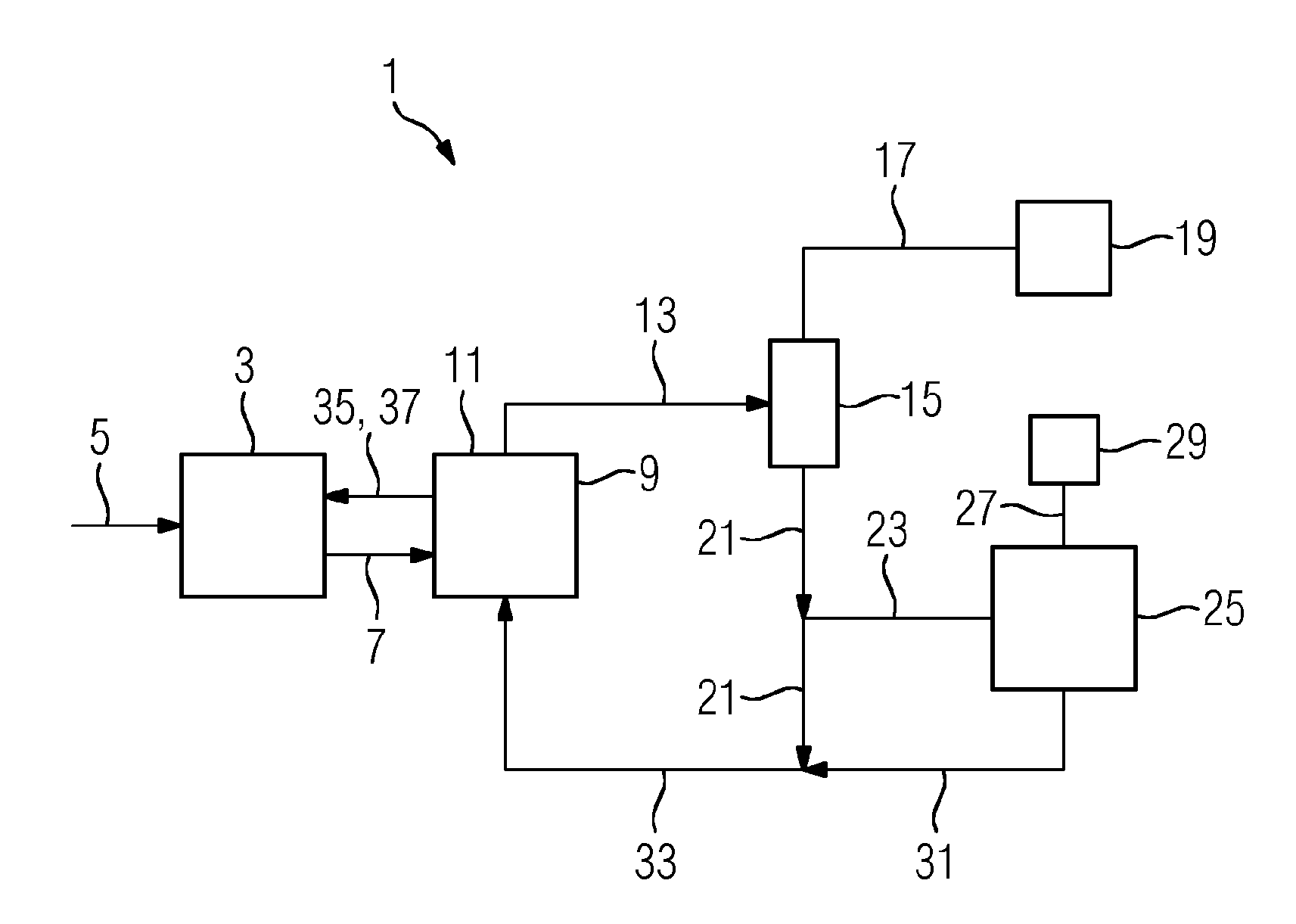
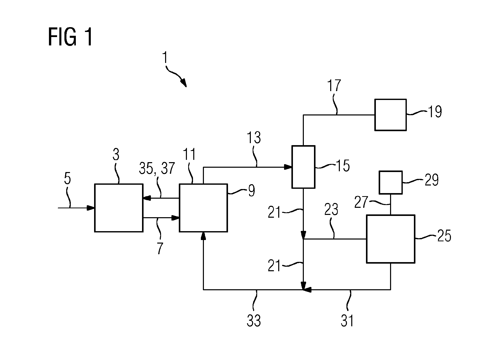
[0056]FIG. 1 shows a schematic depiction of a separating device 1 for separating off carbon dioxide from a flue gas stream. The separating device 1 comprises an absorber 3 for separating off carbon dioxide from the flue gas stream. For this purpose, flue gas is fed to the absorber 3 via a feed line 5, and the carbon dioxide present in the flue gas is brought into contact in the absorber 3 with a scrubbing medium. The carbon dioxide present in the flue gas is absorbed in the scrubbing medium and fed via a feed line 7 to a desorber 9 that is flow-connected to the absorber 3. In the desorber 9, the carbon dioxide absorbed in the scrubbing medium is liberated by temperature elevation.

[0057]Although the amino acid salt used in the present case as scrubbing medium has an extremely low vapor pressure, a small part of the degradation or breakdown products can consist of highly volatile methylamine, which can serve as precursor for the formation of, e.g., dimethylamine. The dimethylamine, in...


PUM

PropertyMeasurementUnit
Degradation propertiesaaaaaaaaaa

Abstract

A method for separating carbon dioxide from a gas flow, in particular from a flue gas flow, where a gas flow is brought in contact with a scrubbing medium in an absorber of a separating device and carbon dioxide contained in the gas flow is separated, the loaded scrubbing medium is fed to a desorber of the separating device in order to release the carbon dioxide, a vapor flow is drawn from the desorber and is fed to a cooling device in order to form condensate, and the condensate formed in the cooling device is at least partially fed to a purifying device, in which degradation products contained in the condensate are removed by reverse osmosis and/or by an ion exchanger. A separating device is adapted for separating carbon dioxide from a gas flow.

Description

CROSS REFERENCE TO RELATED APPLICATIONS[0001]This application is the US National Stage of International Application No. PCT / EP2014 / 062187 filed Jun. 12, 2014, and claims the benefit thereof. The International Application claims the benefit of German Application No. DE 102013211757.4 filed Jun. 21, 2013. All of the applications are incorporated by reference herein in their entirety.FIELD OF INVENTION[0002]The invention relates to a method for separating off carbon dioxide from a gas stream, in particular from a flue gas stream. In addition, the invention relates to a separating device for separating off carbon dioxide from a gas stream, in particular from a flue gas stream.BACKGROUND OF INVENTION[0003]Against the background of climate changes, it is a global aim to decrease the emission of pollutants into the atmosphere. This applies, in particular, to the emission of carbon dioxide (CO2), which collects in the atmosphere, prevents the radiation of heat away from the earth and thus, ...

Claims


Application Information

Patent Timeline
IPC IPC(8): B01D53/14B01D15/36B01D61/02
CPCB01D53/1425B01D61/025B01D2252/20494B01D53/1475B01D15/361B01D15/36B01D53/62B01D53/96B01D2257/504B01D2258/0283B01D2311/04Y02C20/40B01D2311/2626
Inventor HAFNER, BENJAMINKURSAWE, ANSGARREICHL, ALBERTSCHNEIDER, RUDIGERSCHRAMM, HENNING
Owner SIEMENS ENERGY GLOBAL GMBH & CO KG
Why Eureka
Try Eureka