Fluid permeable and vacuumed insulating microspheres and methods of producing the same

a technology of vacuum insulation, which is applied in the field of glass microspheres and methods of producing glass microspheres, can solve the problems of inability to manufacture microspheres and their methods of manufacture, inability to meet the needs of large-scale production, etc., to achieve superior fluid permeable glass microspheres, superior strength, and large surface area

Active Publication Date: 2016-07-21
HOJAJI HAMID +1
View PDF2 Cites 16 Cited by
  • Summary
  • Abstract
  • Description
  • Claims
  • Application Information

AI Technical Summary

Benefits of technology

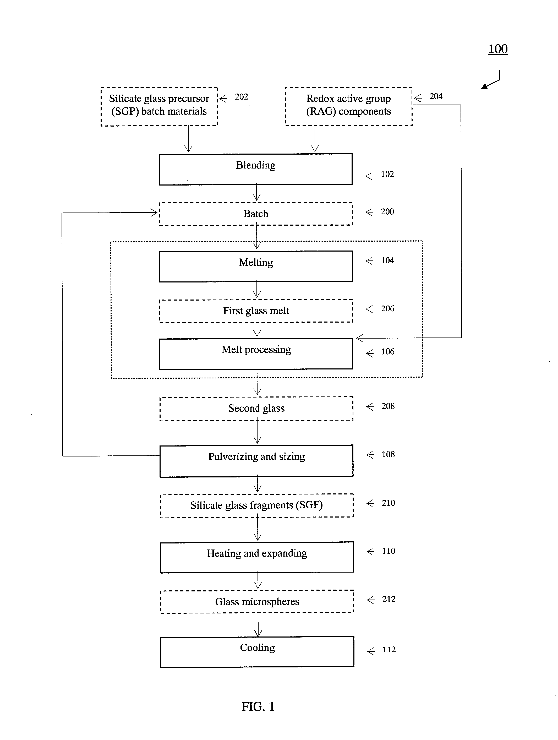
[0236]The atmosphere within the furnace employed for heating and expanding the silicate glass fragments 210, in accordance with the present invention, is controlled to be either neutral, oxidizing, or reducing. When the furnace is operated under neural to mildly reducing conditions the relative concentration of thermal NOx in the flu gases is decreased, which is environmentally advantageous. Another advantage of the present invention is due to having the ability to lower the melting temperature of the second glass 208 compared to the first glass 206. Yet another advantage of the present invention is the ability to generate gas in the second glass 208 from multiple sources. All the advantages above lead to the ability of lowering the firing temperature requirements for the second glass that in turn results in improving the fuel efficiency of the manufacturing process, and hence the ability of economically manufacturing high quality hollow glass microspheres 212.
[0237]The sulfide compounds of the RAG components 204 include both synthetic and mineral compounds of sulfides. According to the present invention, in addition to or instead of sulfides, selenides, antimonides, bismuthinides, and sulfosalts may also be used, but they are normally more costly than the synthetic and mineral compounds of sulfides containing S2−. Examples of the sulfide compounds that are used according to the present invention are one or a combination of acanthite Ag2S, chalcocite Cu2S, bornite Cu5FeS4, galena PbS, sphalerite ZnS, chalcopyrite CuFeS2, pyrrhotite FeS, millerite NiS, pentlandite (Fe,Ni)9S8, covellite CuS, stibnite Sb2S3, pyrite FeS2, molybdenite MoS2, and other metal and transition metal sulfides. Iron sulfide, with the general formula Fe1-xS, is one sulfide compound to be used according to one embodiment of the present invention, wherein x varies from zero to 0.5. Iron sulfide, for example, in the form of pyrite, is readily commercially available at relatively low cost. Another source of iron sulfide is from vitreous, semi-vitreous, or crystalline industrial byproducts such as incineration slag, incineration ash, bottom ash, and flyash. Ferric sulfide is also acceptable.
[0238]In accordance with one embodiment of the present invention, all or a portion of the materials that constitute the batch 200 are derived from recovered materials. As disclosed earlier in this document, the “recovered materials” are waste materials, either of hazardous or non-hazardous nature. Converting non-hazardous recovered materials to hollow glass spheres provides a highly value added product, while preserving natural resources, by decreasing the demand for mined raw materials. Exemplarily, asbestos containing waste materials, in accordance with the present invention are melted as a part of the batch 200 into the first glass 206 in the melting zone 310. Any adjustments to the RAG components are carried out either via batch 200 and / or inside the melter system 300 such as in the melting zone 310, the processing zone 320, and the discharge zone 330. In this way, not only a hazardous waste material is safely vitrified, but also the resulting vitrified material forms a second glass 208, which is suitable to be converted to high quality glass microspheres 212. The embodiment of the invention disclosed above for the asbestos containing waste materials is equally applicable for other waste materials, such as incineration ash, radioactive waste materials, and any other vitrifiable waste materials.
[0239]In accordance with one embodiment of the present invention, a vitrified waste material that has a combination of RAG components and / or RAG components reaction products, such as at least one sulfur compound, and a multivalent metal, is used directly as the second glass 208 from which silicate glass fragments 210 are made. Accordingly, the vitrified waste material is pulverized and sized in step 108, forming the plurality of silicate glass fragments 210. The resulting silicate glass fragments 210 are heated in step 110 to form glass microspheres 212, which in this case are directly produced from pulverization of a vitrified waste material. Exemplary vitrified waste materials to be used as the second glass 208 are: vitrified asbestos waste materials, vitrified hazardous waste materials, vitrified radioactive waste materials, vitrified incinerated municipal waste materials, vitrified incineration ash, and vitrified medical waste materials.
[0240]Converting hazardous materials into non-hazardous recovered materials, and then into glass microspheres provides better handling, more efficient storing, and the possibility of reuse of the recovered materials. Examples of a non-hazardous (land fillable) industrial byproducts used are fly ash, bottom ash, and in some cases incineration ash. Examples of hazardous materials converted into non-hazardous recovered materials and consequently into glass microspheres, are asbestos containing waste materials, and medical / municipal waste materials that are vitrified into essentially non-hazardous glassy materials. Another example of a hazardous industrial byproduct is vitrified nuclear waste that despite being considered radioactive, the radioactive isotopes contained in it, are securely fixed into the molecular structure of the glass, resulting in glasses that are chemically very durable and physically highly stable. The vitrified nuclear waste glass is used as the second glass 208 in accordance with the present invention to manufacture radioactive glass microspheres. Most of the vitrified low-level nuclear glasses contain RAG components 204, in the form of iron oxide, and sulfur compounds. The glass microspheres 212 are essentially solid when there is not sufficient gas forming RAG components 204 present. On the other hand, the microspheres are hollow when there is sufficient gas forming RAG components 204 present. The resulting glass microspheres find uses in many applications, including radiation source miniaturization, medical applications, etc.
[0241]According with an embodiment of the present invention, the vitrified hazardous waste materials are used instead of batch 200 to create the first glass 206. In certain cases when sufficient RAG components 204 (or RAG reaction products) are already present in the vitrified hazardous waste materials, they are treated as the second glass 208, and further processed in accordance with the steps 108, 110, and 112 to manufacture corresponding glass microspheres. The resulting glass microspheres created in accordance with this embodiment of the invention, find use in many applications that require an inexpensive, and high performance filler particles for composites. Another example of post-consumer non-hazardous consumer byproducts that may be used instead of or in addition to the batch 200 is incineration ash resulting from incinerating waste materials.

Problems solved by technology

Such porous microspheres with reduced internal structure are not available in the art and their methods of manufacture are as well not available in the art.
Such microspheres and their methods of manufacture are not available in the art.

Method used


Image

  • Fluid permeable and vacuumed insulating microspheres and methods of producing the same
  • Fluid permeable and vacuumed insulating microspheres and methods of producing the same
  • Fluid permeable and vacuumed insulating microspheres and methods of producing the same

Examples


example 1

[0243]This example describes an embodiment of the present invention in which fly ash is used as a part of the batch 200. Additionally, the present example illustrates the embodiment of the present invention wherein the RAG components 204 are intrinsic and / or integral to the SGP raw materials 202.

[0244]Fly ash is an industrial byproduct that falls into the category of materials defined herein as “recovered materials”. ASTM C618 provides two types of fly ash classifications: Class F: SiO2+Al2O3+Fe2O3≧70%, and Class C: SiO2+Al2O3+Fe2O3≧50%. All in wt %.

[0245]The RAG components in fly ash comprise unburned carbon, which can vary from 0.2 to as high as 3.5 wt %, in addition to iron oxides, and sulfur compounds. Iron oxides are almost always present in fly ash, mostly in the form of magnetite (FeO+Fe2O3) and sulfur in the forms of sulfates, sulfites, or sulfides.

[0246]A typical class F fly ash, has less sulfur than a class C fly ash. The initial content of sulfur as sulfate in the flyash ...

example 2

[0255]In accordance with a further example of the present invention, a municipal waste incineration-ash, and / or a medical waste incineration-ash, is used as a part of the SGP raw materials. Silica flour is added in order to increase the silica content of the composite batch 200. As a part of the RAG components 204, gypsum is added to the batch 200 to adjust the sulfate content to achieve a prescribed chemical composition for the first glass melt 206. The resulting batch 200 is melted in the same type melter system that is employed in the Example 1. Hydrogen sulfide, with and without a carbonaceous RAG component 204, such as graphite is incorporated into the first glass melt 206 while in the melter system 300, in order to control the gas volume generated in the second glass melt 208 via the redox reactions while in the furnace. The first glass melt 206 is discharged from the melter system 300, cooled, and pulverized to form the silicate glass fragments 210. The newly formed silicate ...

example 3

[0256]In yet another example of the present invention, a vitrified low level radioactive waste material is treated as the second glass 208. The second glass 208 is a borosilicate-based glass. The solid pieces of the second glass 208 are pulverized and screened to obtain the desired silicate glass fragments 210. The silicate glass fragments are fired in a firing furnace that has suitable off gas treatment capabilities for radioactive gaseous and particulate emissions. The firing temperature is set around 1200-1400° C. The resulting radioactive glass microspheres 212 are chemically durable and stable. The radioactive glass microspheres may be used as a radiation source, for example in medical applications. In addition, the radioactive glass microspheres can be reused, and repackaged easily as a flowable solid material.


PUM

PropertyMeasurementUnit
particle densityaaaaaaaaaa
pore diameteraaaaaaaaaa
particle densityaaaaaaaaaa

Abstract

Microsphere comprising an outer shell enclosing a substantially hollow inner space, the outer shell comprising a fluid permeable porous structure, the fluid permeable porous structure comprising interconnected pores, the microsphere being capable of maintaining a vacuum in its substantially hollow inner space when its outer shell is sealed.

Description

FIELD OF INVENTION[0001]The present invention is directed to glass microspheres and methods of producing glass microspheres. More specifically, the present invention is directed to glass microspheres with a non-porous outer shell made from redox active glass, and their methods of manufacture, to fluid permeable glass microspheres and their methods of manufacture, and to vacuumed insulating microspheres and their methods of manufacture.BACKGROUND OF THE INVENTION[0002]Various methods are already known in the art for the manufacture of glass microspheres. In accordance with the methods available in the art, pre-formed glass particles may be converted into glass bubbles or micro-balloons. To create the glass bubbles, the glass particles have to be post-modified to contain the ingredients necessary for their expansion.[0003]As known from the art, a silicate glass with over 14 wt % sodium oxide and 0.1 Fe2O3 is initially treated with high temperature steam and is used to form glass bubbl...

Claims


Application Information

Patent Timeline
Patent Type & Authority Applications(United States)
IPC IPC(8): C03B19/10C03C12/00
CPCC03B19/10C03B5/005C03B5/031C03B5/193C03B5/2356C03B19/107C03B19/1095C03C11/002Y10T428/2982Y02P40/50C08K7/28
Inventor HOJAJI, HAMIDKOCS, LAURA GABRIELA
Owner HOJAJI HAMID
Why Eureka
Try Eureka