
Direct injection fuel pump system

a fuel pump and direct injection technology, applied in the direction of liquid fuel engines, machines/engines, positive displacement liquid engines, etc., can solve the problems of excessive nvh generated by ticks, affecting the lubrication increasing wear and tear of the di fuel pump, so as to improve the vaporization of fuel, improve the torque and fuel economy, and improve the effect of engine performan

Inactive Publication Date: 2016-07-21
FORD GLOBAL TECH LLC
View PDF2 Cites 12 Cited by
  • Summary
  • Abstract
  • Description
  • Claims
  • Application Information

AI Technical Summary

Benefits of technology

The patent text discusses the challenges with direct injection engines, such as excessive noise and vibration during engine starting and reduced durability of the fuel pump due to fuel heating. The inventors found a solution to these issues by maintaining a default pressure in the fuel pump and using an accumulator to lubricate the piston-bore interface and reduce fuel heating. This solution not only improves engine performance but also increases fuel pump durability.

Problems solved by technology

Further, the direct injection (DI) fuel pump may be deactivated during certain periods of engine operation (e.g., during port fuel injection at low engine loads, engine idle conditions) which may affect lubrication of the DI fuel pump and increase wear, NVH, and degradation of the DI fuel pump.
For example, in the approach where direct injection is continued at lower engine loads, excessive NVH may be generated from ticks resulting from the actuation of the solenoid activated check valve in the DI fuel pump.
Further, in the approach wherein the compression chamber in the DI fuel pump is maintained at default pressure by the pressure relief valve, fuel heating may occur due to repeated fuel flow through the pressure relief valve.
Furthermore, an increase in the temperature of the fuel may cause formation of fuel vapor, which can adversely affect pump lubrication.
Further still, fuel heating may increase power consumption.

Method used


Image

  • Direct injection fuel pump system
  • Direct injection fuel pump system
  • Direct injection fuel pump system

Examples


Embodiment Construction

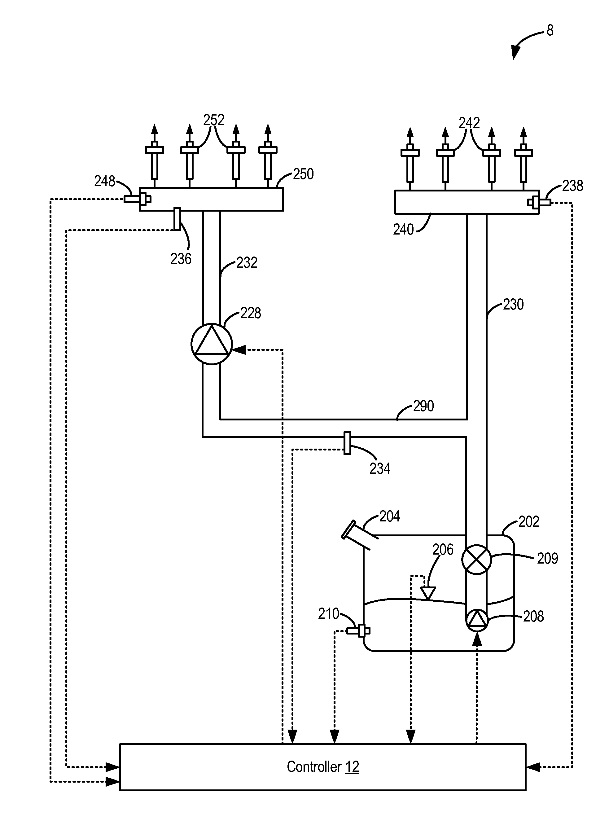
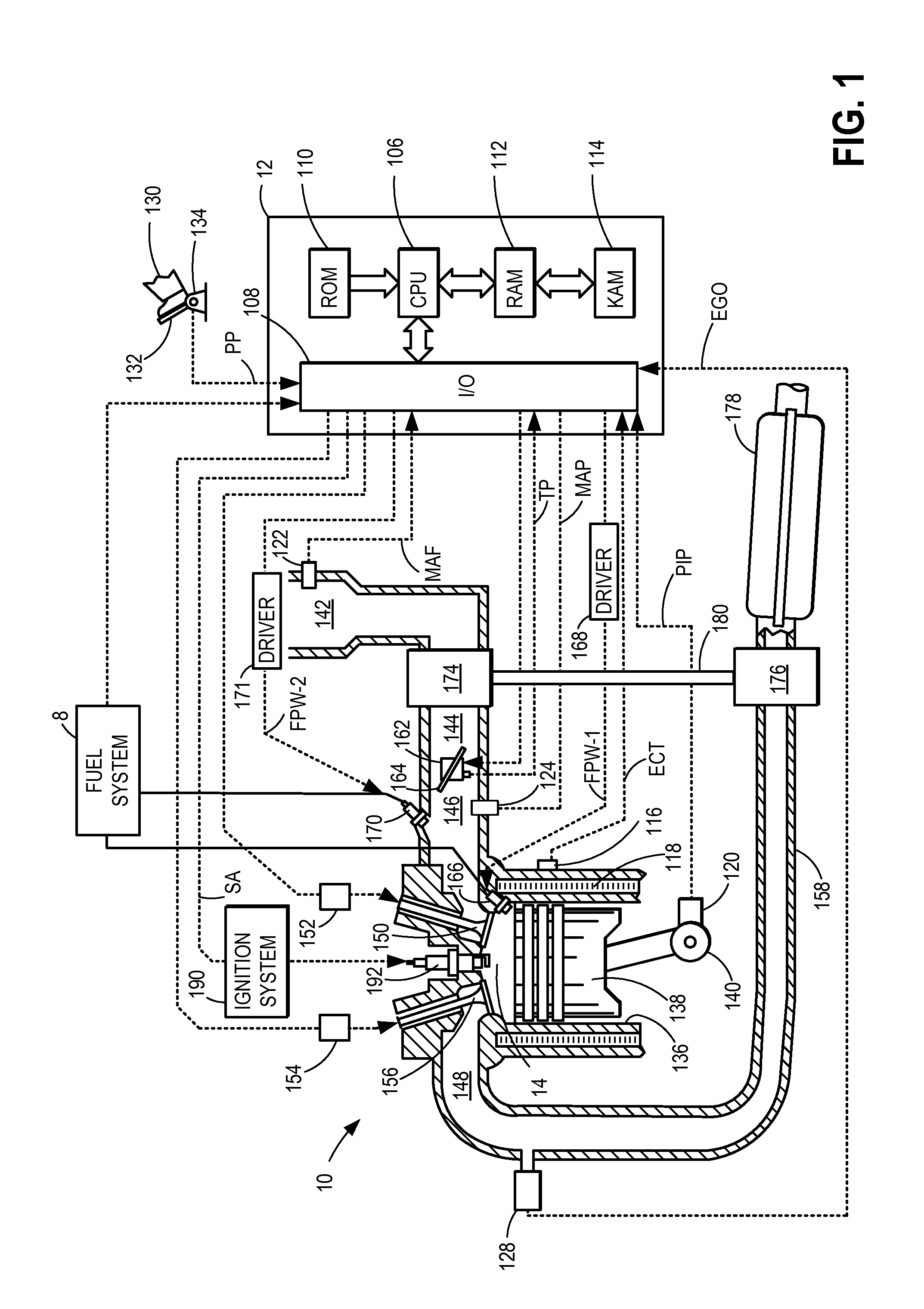
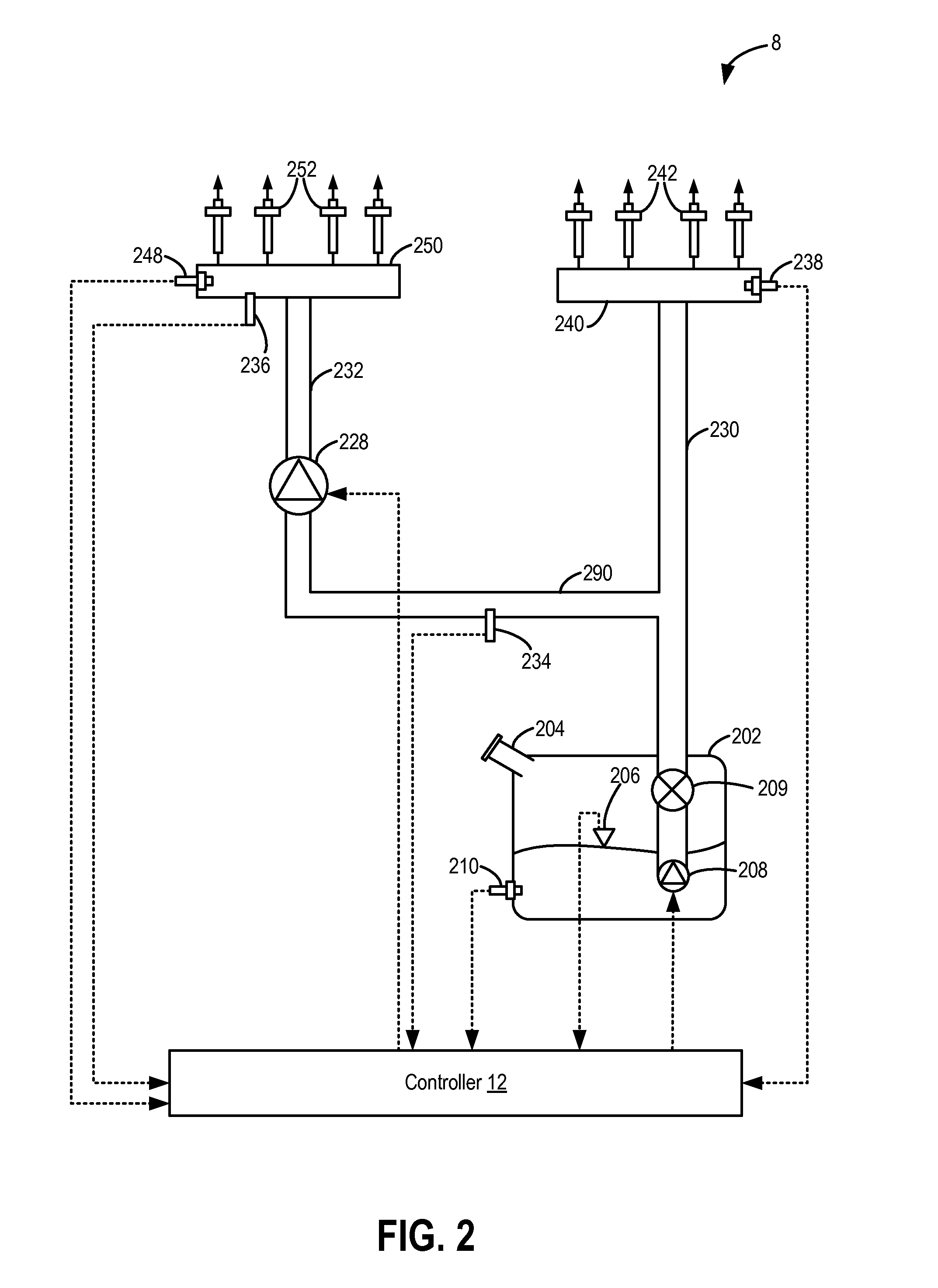
[0022]In port fuel direct injection (PFDI) engines, a fuel delivery system may include multiple fuel pumps for providing a desired fuel pressure to the fuel injectors. As one example, the fuel delivery system may include a lower pressure fuel pump (or lift pump) and a higher pressure (or direct injection) fuel pump arranged between a fuel tank and fuel injectors. The higher pressure fuel pump may be coupled to upstream of a high pressure fuel rail in a direct injection system to raise a pressure of the fuel delivered to engine cylinders through direct injectors. A solenoid activated inlet check valve, or spill valve, may be coupled upstream of the high pressure (HP) pump to regulate fuel flow into a compression chamber of the high pressure pump. The spill valve is commonly electronically controlled by a controller which may be part of a control system for the engine of the vehicle. Furthermore, the controller may also have a sensory input from a sensor, such as an angular position s...


PUM


Abstract

Systems and methods are provided for operating a direct injection fuel pump. One example system comprises an accumulator positioned within a bore of the direct injection fuel pump in a coaxial manner wherein the accumulator is positioned downstream from a solenoid activated check valve. The accumulator may regulate pressure in a compression chamber of the direct injection fuel pump and a high pressure fuel rail when the direct injection fuel pump is operating in a default pressure mode.

Description

FIELD[0001]The present application relates generally to a direct injection fuel pump in an internal combustion engine.BACKGROUND AND SUMMARY[0002]Port fuel direct injection (PFDI) engines include both port injection and direct injection of fuel and may advantageously utilize each injection mode. For example, at higher engine loads, fuel may be injected into the engine using direct fuel injection for improved engine performance (e.g., by increasing available torque and fuel economy). At lower engine loads and during engine starting, fuel may be injected into the engine using port fuel injection to provide improved fuel vaporization for enhanced mixing and to reduce engine emissions. Further, port fuel injection may provide an improvement in fuel economy over direct injection at lower engine loads. Further still, noise, vibration, and harshness (NVH) may be reduced when operating with port injection of fuel. In addition, both port injectors and direct injectors may be operated togethe...

Claims


Application Information

Patent Timeline
IPC IPC(8): F02M59/02F04B19/22F04B53/16F04B53/10F04B53/14F02M55/02F04B11/00
CPCF02M59/022F02M55/025F04B19/22F04B53/16F04B53/10F04B53/14F04B11/0033F02M47/02F02M59/367F02M63/0001F02M63/0265F02M2200/40F02M63/029F02M55/02F02M59/102F02M2200/09F02M2200/02F04B11/0016F04B53/144F02M59/00
Inventor PURSIFULL, ROSS DYKSTRAVANDERWEGE, BRAD ALAN
Owner FORD GLOBAL TECH LLC
Learn More