
Triboelectric pressure sensing cable and preparation method thereof

a technology of pressure sensing cable and triboelectric pressure, which is applied in the direction of cables, cables, cables, etc., can solve the problems that the new pressure sensing cable with higher output signal strength becomes an urgent technical problem, and achieves compact structure, high stability, and easy and convenient operation.

Inactive Publication Date: 2016-07-21
NAZHIYUAN TECH TANGSHAN LLC
View PDF7 Cites 22 Cited by
  • Summary
  • Abstract
  • Description
  • Claims
  • Application Information

AI Technical Summary

Benefits of technology

This patent describes a new type of pressure sensing cable that is made up of a central conducting wire, an insulating layer, an electrode layer, and an insulating outer layer. The cable can change its shape when exposed to external factors, which results in the generation of signals that can be measured to achieve the goal of monitoring. Compared to conventional cables, the triboelectric pressure sensing cable described in this patent has greater signal strength without the need for high input impedance circuits or charge amplifiers. Additionally, the method for preparing this cable is easy and convenient. The cable has a compact structure, is highly stable, and has a long lifetime with marked effects.

Problems solved by technology

Despite such a wide application range of the pressure cable, it has disadvantages of high impedance and weak signals, so a high input impedance circuit or charge amplifier is required to overcome these disadvantages.
Therefore, the development of a new pressure sensing cable with higher output signal strength becomes an urgent technical problem for industry insiders.

Method used


Image

  • Triboelectric pressure sensing cable and preparation method thereof
  • Triboelectric pressure sensing cable and preparation method thereof
  • Triboelectric pressure sensing cable and preparation method thereof

Examples


example 1

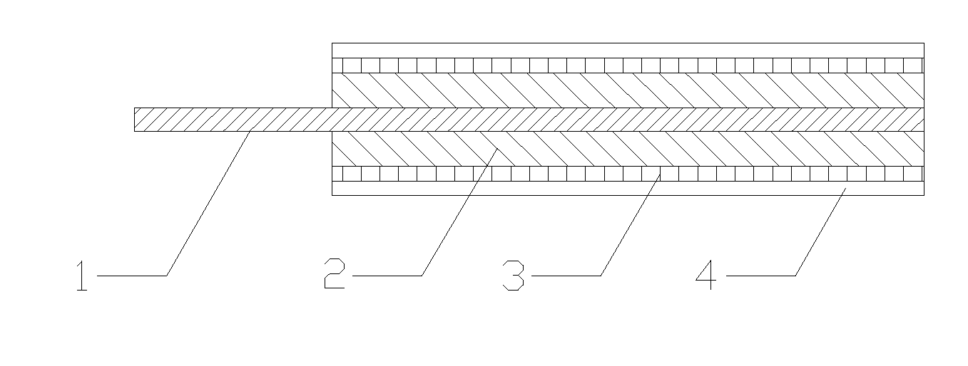
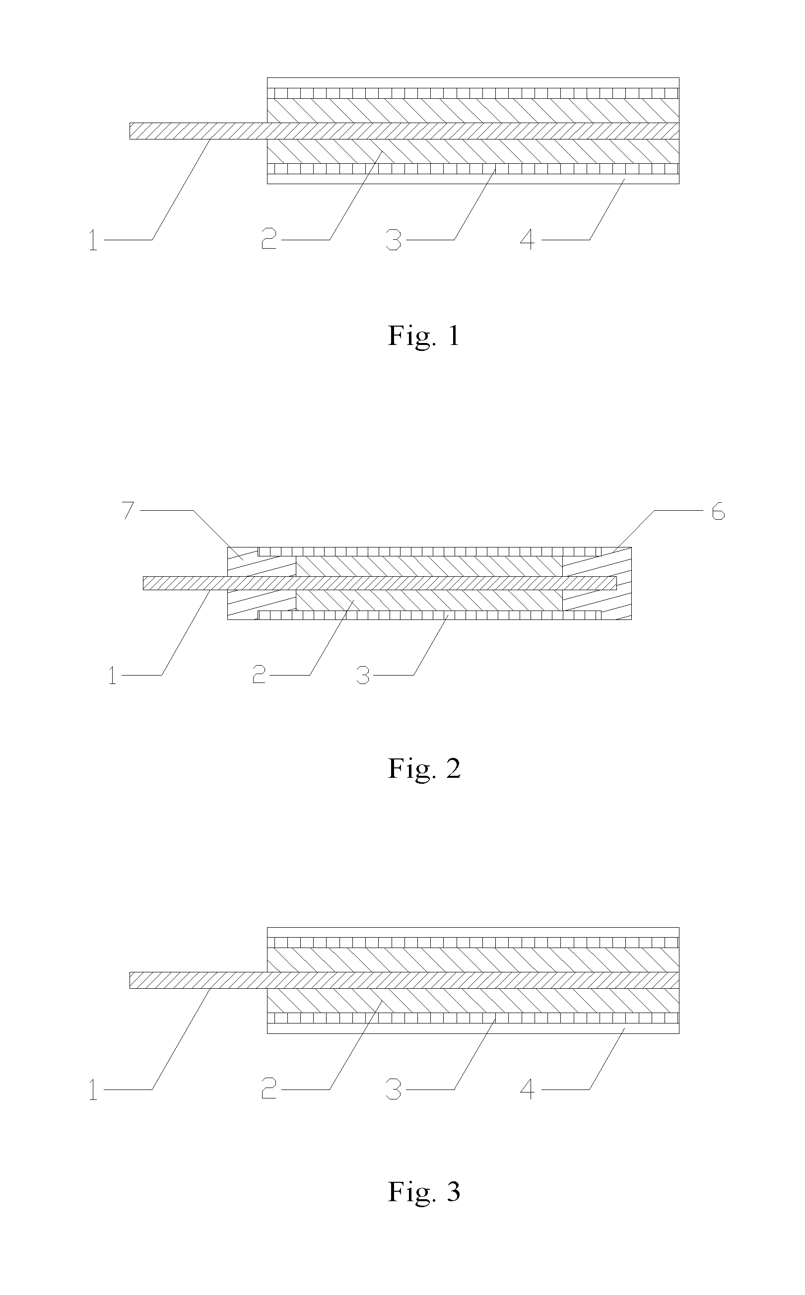
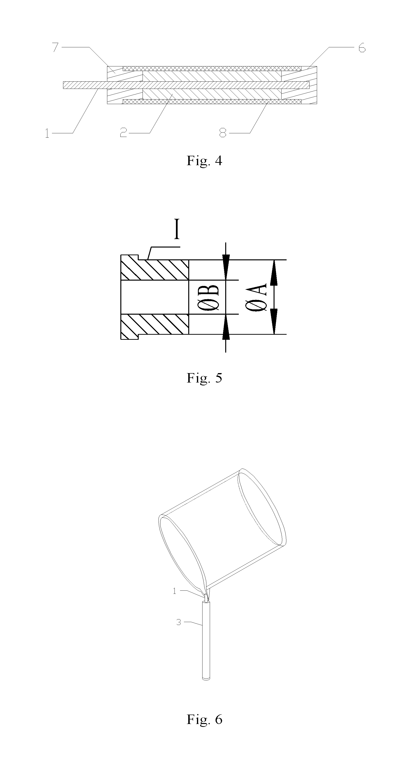
[0108]As is shown in FIG. 1, the structure of the prepared triboelectric pressure sensing cable was as follows: a central conducting wire (1), a high-molecular polymer insulating layer (2), an electrode layer (3), and an insulating outer layer (4), which were coaxially arranged from inside to outside.

[0109]The preparation method of the triboelectric pressure sensing cable was illustrated with reference to FIG. 2, one end of the cable was the blind-hole plug (6) and the other end of the cable was the through-hole plug (7).

[0110]The preparation method comprised the steps of:

[0111]500 g of PDMS was added with the curing agent Dow Corning 184 in ratio of 10:1, mixed well, and placed in vacuum drier. Air dissolved in PDMS was vacuumed.

[0112]A copper central conducting wire with a diameter of 5 mm was selected. A blind-hole plug was mounted at one end of the central conducting wire, and a through-hole plug was mounted at a distance of 20 cm. The cross-section shapes of the through-hole pl...

example 2

[0113]As is shown in FIG. 3, the structure of the prepared triboelectric pressure sensing cable was as follows: a central conducting wire (1), a high-molecular polymer insulating layer (2), an electrode layer (3), and an insulating outer layer (4), which were coaxially arranged from inside to outside. The electrode layer (3) had a network structure.

[0114]The preparation method of the triboelectric pressure sensing cable was illustrated with reference to FIG. 4, which is a structural drawing without removal of the blind-hole plug, the through-hole plug and the auxiliary structure for preparing the cavity. One end of the cable was the blind-hole plug (6), the other end of the cable was the through-hole plug (7), and the flexible hollow tube (8) was arranged outside of the high-molecular polymer insulating layer (2). The preparation method comprised the steps of:

[0115]500 g of PDMS was added with the curing agent Dow Corning 184 in ratio of 100:1, mixed well, and placed in vacuum drier...

example 3

[0117]As is shown in FIG. 7, the triboelectric pressure sensing cable comprised a central conducting wire (1), a high-molecular polymer insulating layer (2), an electrode layer (3), a shielding layer (5), and an insulating outer layer (4), which were coaxially arranged from inside to outside.

[0118]The preparation method comprised the steps of:

[0119]500 g of PDMS was added with the curing agent Dow Corning 184 in ratio of 100:20, mixed well, and placed in vacuum drier. Air dissolved in PDMS was vacuumed.

[0120]A copper central conducting wire with a diameter of 5 mm was selected. A blind-hole plug was mounted at one end of the central conducting wire, and a through-hole plug was mounted at a distance of 20 cm. The cross-section shapes of the through-hole plug (6) and the blind-hole plug (7) were the same. The upper surface and lower surface of the plugs of the two ends were used as end surfaces respectively. Copper tape coated with conducting resin was winded on the end surface I of t...


PUM

PropertyMeasurementUnit
Fractionaaaaaaaaaa
Fractionaaaaaaaaaa
Fractionaaaaaaaaaa

Abstract

Provided is a triboelectric pressure sensing cable. The triboelectric pressure sensing cable comprises a central conducting wire, a high-molecular polymer insulating layer, an electrode layer, and an insulating outer layer, which are coaxially attached in sequence. The central conducting wire and the high-molecular polymer insulating layer, and / or the high-molecular polymer insulating layer and the electrode layer separately generate signals by the means of triboelectric effect. Also provided is a method for preparing the triboelectric pressure sensing cable. The method comprises the steps of (1) preparing a high-molecular polymer solution; (2) forming a hollow cavity framework used for casting; (3) casting; (4) molding; and (5) forming an insulating outer layer so as to obtain the triboelectric pressure sensing cable. The provided triboelectric pressure sensing cable can achieve a monitoring effect which is the same as that of a conventional pressure cable, without requiring a high input impedance circuit or a charge-amplifier.

Description

FIELD OF THE INVENTION[0001]The present invention relates to a pressure cable, and particularly to the technical field of the preparation of a triboelectric pressure sensing cable.BACKGROUND[0002]With the development of science and technology, the pressure cable has been greatly developed in the past few decades and widely used in various industrial control environment, such as water conservancy and hydropower, railway traffic, intelligent buildings, production control, aerospace, military, petrochemical, oil well, electric power, ships, machine tools, pipelines, medical and many other industries.[0003]The output of an ordinary pressure cable is an analog signal, which refers to continuous signals presented by information parameters within a given range, or signals of any values presented at any moment in a continuous interval by the characteristic quantity of the information represented by the parameters. However, the commonly used pressure cable is made by using the piezoelectric ...

Claims


Application Information

Patent Timeline
IPC IPC(8): G01L1/00B05D1/26H01B7/02H01B13/08H01B7/00H01B3/30
CPCG01L1/005H01B7/0009B05D1/26H01B7/02H01B13/08H01B3/30G01L1/16G01L1/142G01L5/0061
Inventor HUS, CHARLESZHAO, HAOHAO, LIXINGWANG, ZHULANG, JIAXINGSUN, LIJIA
Owner NAZHIYUAN TECH TANGSHAN LLC
Learn More