Method for providing lithographic printing plates

a technology of lithographic printing plate and precursor, which is applied in the field of processing imaged printing plate precursor, can solve the problems of increasing the amount of waste at the customer site, premature replacement by operators, and significant contaminants of colouration dye or pigment within the developer unit, so as to reduce the colouration of processing solutions and high image contrast

Inactive Publication Date: 2016-07-28
AGFA NV
View PDF4 Cites 5 Cited by
  • Summary
  • Abstract
  • Description
  • Claims
  • Application Information

AI Technical Summary

Benefits of technology

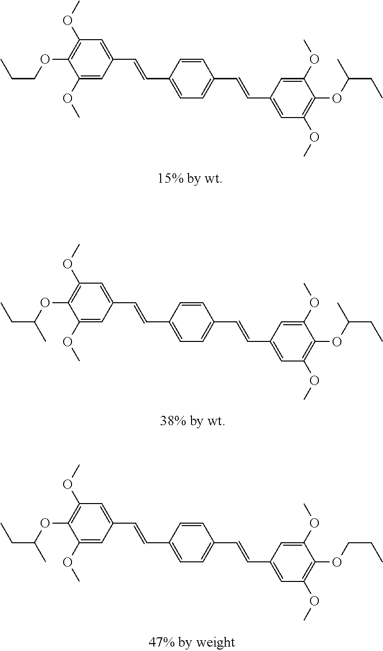
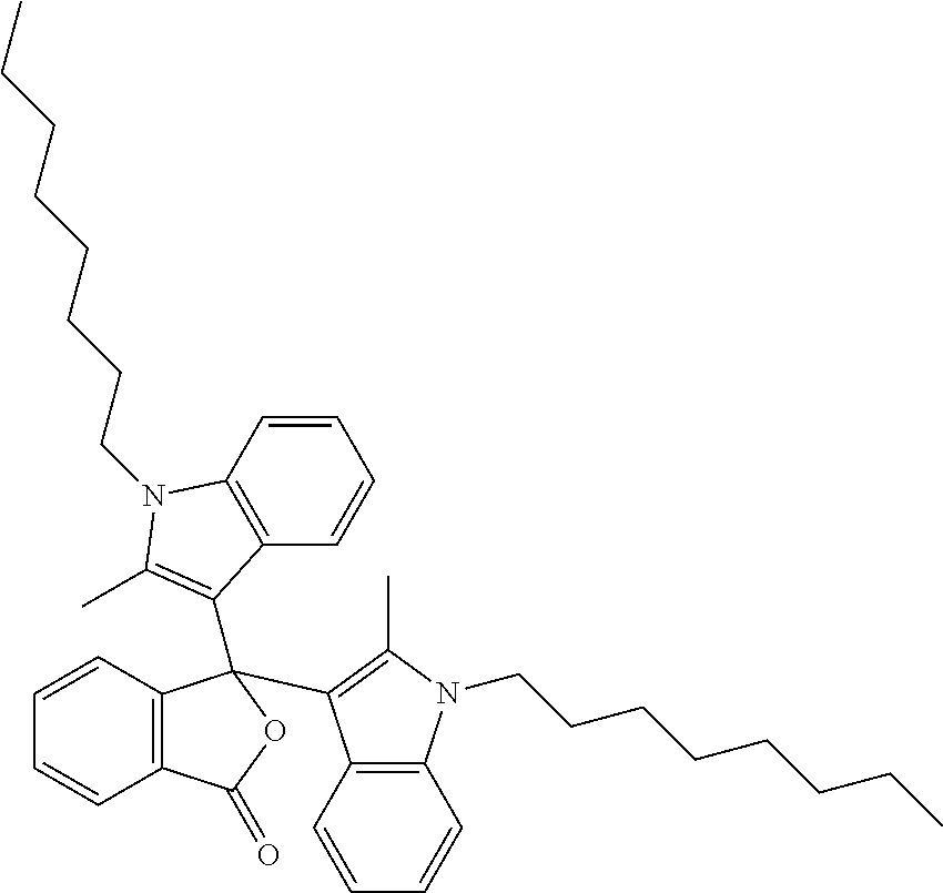
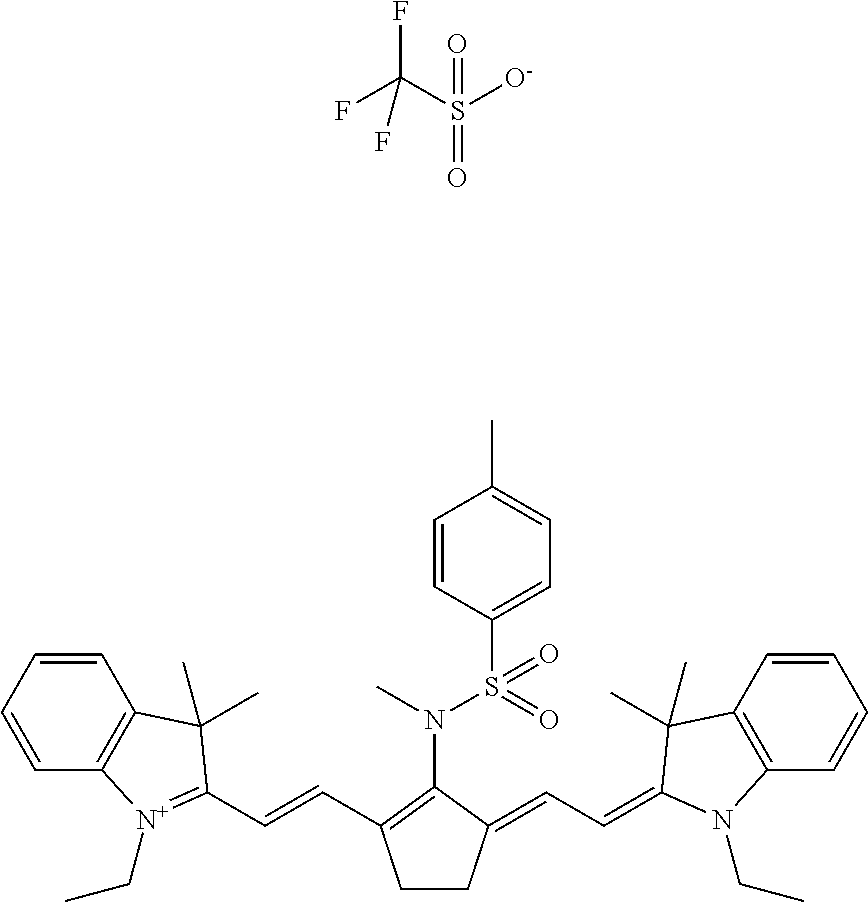
[0019]Therefore, preferred embodiments of the present invention provide a solution for reduced colouration of processing solutions upon processing positive or negative working printing plate precursors and hence preserve a high image contrast between the printing and non-printing areas of the printing plate. This has been achieved by a method of making a lithographic printing plate comprising the steps of: a) image-wise exposing a lithographic printing plate precursor wherein the printing plate precursor comprises a hydrophilic support and a coating comprising a colorant precursor, ...

Problems solved by technology

Although some plate precursors are capable of producing a lithographic image immediately after exposure, the most popular lithographic plate precursors require wet processing since the exposure produces a difference in solubility or difference in rate of dissolution in a developer between the exposed and the non-exposed areas of the coating.
It is a well known phenomenon that offset lithographic printing plate precursors containing a coating with sufficient colouration in order to generate printing plates that have image parts that are visible and measurable after processing, can leave significant contaminants of the colouration dye or pigment within the developer unit, the rinsing unit and the gumming unit.
Dye residues turn the processing solutions, being the developer, rinsing solution or gum coloured and cannot be so easily removed.
After processing an amount of lithographic printing plate precursors, the accumulation of the colorant in the processing solutions is leading to very dark coloured solutions, which ultimately may lead t...

Method used


Image

  • Method for providing lithographic printing plates
  • Method for providing lithographic printing plates
  • Method for providing lithographic printing plates

Examples


examples

1. Preparation of the Printing Plate Precursors

Preparation of the Aluminium Support S-01

[0090]A 0.3 mm thick aluminium foil was degreased by spraying with an aqueous solution containing 26 g / l NaOH at 65° C. for 2 seconds and rinsed with demineralised water for 1.5 seconds. The foil was then electrochemically grained during 10 seconds using an alternating current in an aqueous solution containing 15 g / l HCl, 15 g / l SO42− ions and 5 g / l Al3+ ions at a temperature of 37° C. and a current density of about 100 A / dm2. Afterwards, the aluminium foil was then desmutted by etching with an aqueous solution containing 5.5 g / l of NaOH at 36° C. for 2 seconds and rinsed with demineralised water for 2 seconds. The foil was subsequently subjected to anodic oxidation during 15 seconds in an aqueous solution containing 145 g / l of sulfuric acid at a temperature of 50° C. and a current density of 17 A / dm2, then washed with demineralised water for 11 seconds and post-treated for 3 seconds (by spray) w...


PUM


Abstract

A method of making a lithographic printing plate includes the steps of a) image-wise exposing a lithographic printing plate precursor including a hydrophilic support and a coating containing a colorant precursor to form a lithographic image consisting of printing areas and non-printing areas, b) developing the plate precursor to remove the coating in the non-printing areas from the support, and c) drying the plate precursor, and d) subjecting the plate precursor to heat or radiation to induce a colour change of the coating in the printing areas, wherein before step b) the coating in the non-printing areas and the support are characterised by a CIE 1976 colour difference ΔE1 which is 5.0 or less, and after step d) the CIE 1976 colour difference ΔE2 between the coating in the printing areas and the non-printing areas is more than 6.8.

Description

CROSS-REFERENCE TO RELATED APPLICATIONS[0001]This application is a 371 National Stage Application of PCT / EP2014 / 070760, filed Sep. 29, 2014. This application claims the benefit of European Application No. 13188632.7, filed Oct. 15, 2013, which is incorporated by reference herein in its entirety.BACKGROUND OF THE INVENTION[0002]1. Field of the Invention[0003]The invention relates to a method of processing imaged printing plate precursors.[0004]2. Description of the Related Art[0005]Lithographic printing typically involves the use of a so-called printing master such as a printing plate which is mounted on a cylinder of a rotary printing press. The master carries a lithographic image on its surface and a print is obtained by applying ink to said image and then transferring the ink from the master onto a receiver material, which is typically paper. In conventional lithographic printing, ink as well as an aqueous fountain solution (also called dampening liquid) are supplied to the lithog...

Claims


Application Information

Patent Timeline
IPC IPC(8): B41C1/10
CPCB41C1/1091B41C1/1008B41C1/1025G03F7/105B41C2210/02B41C2210/04B41C2210/06B41C2210/08B41C2210/12B41C2210/22G03F7/322B41M5/28
Inventor HENDRIKX, PETERCALLANT, PAULSTEENACKERS, MARINVERBRUGGHE, SAM
Owner AGFA NV
Why Eureka
Try Eureka