Wheel support device for vehicle

a technology for supporting devices and vehicles, applied in mechanical devices, couplings, transportation and packaging, etc., can solve the problems of reducing lubricant, grease cannot be effectively prevented from being electrically charged, and charging cannot be moved from the race members to the surrounding members, so as to achieve convenient fixation, enhance the effect of neutralization, and efficiently perform

Active Publication Date: 2016-08-04
TOYOTA JIDOSHA KK
View PDF11 Cites 14 Cited by
  • Summary
  • Abstract
  • Description
  • Claims
  • Application Information

AI Technical Summary

Benefits of technology

[0027]According to the arrangement as described above, the metal foil that eliminates charge can be easily fixed by bonding to the surface of the particular member. Further, the metal foil adheres to the particular member via the layer of the adhesive that covers the entire area of the metal foil. Therefore, transfer of electric charges from the particular member to the metal foil can be efficiently performed, and the effect of neutralization can be enhanced.

Problems solved by technology

However, in a situation where the vehicle body, etc. are electrically charged, members surrounding the bearing device are also electrically charged, and therefore, charges cannot be moved from the race members to the surrounding members.
Therefore, the grease cannot be effectively prevented from being electrically charged.
If the lubricant is electrically charged, the freedom of molecules of the lubricant is reduced, presumably resulting in an increase of the viscosity of the lubricant.

Method used


Image

  • Wheel support device for vehicle
  • Wheel support device for vehicle
  • Wheel support device for vehicle

Examples


first exemplary embodiment

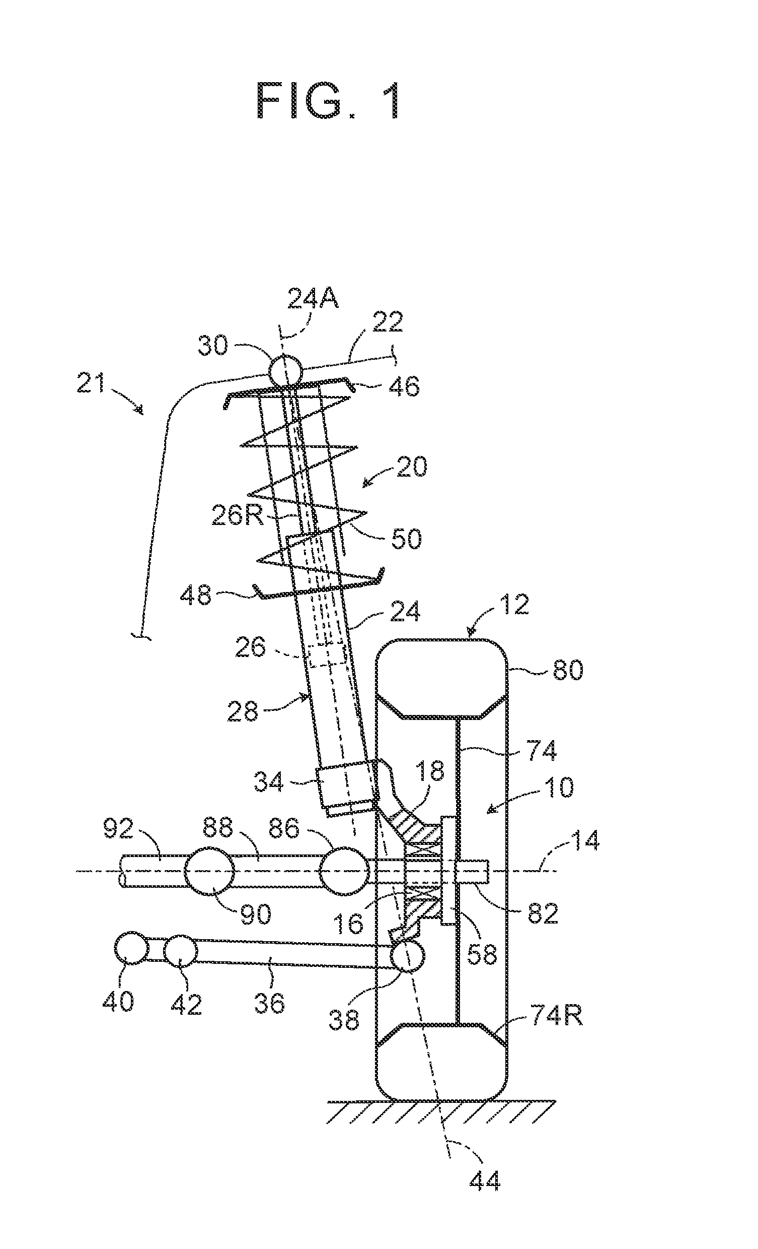
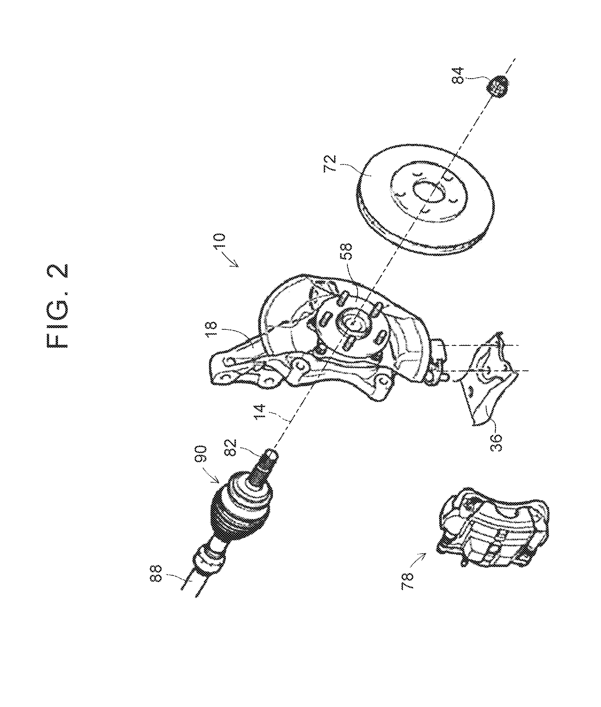
[0040][First Exemplary Embodiment]FIG. 1 is a schematic view showing a wheel support device 10 according to the invention, as viewed from the rear of a vehicle. The wheel support device 10 is used for a McPherson strut type front suspension. FIG. 2 is an exploded, perspective view showing a part of the wheel support device 10 shown in FIG. 1.

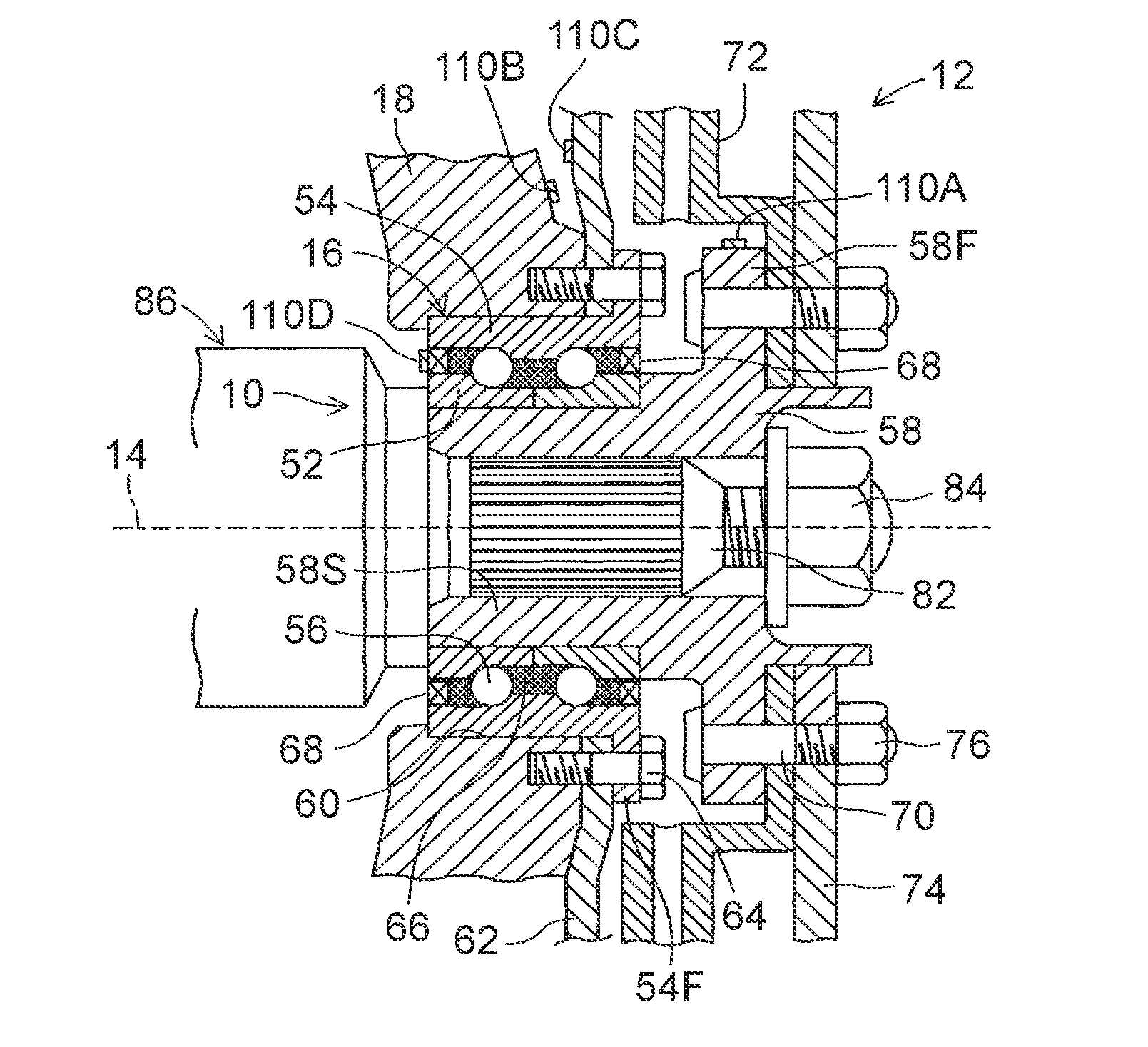
[0041]In these figures, the wheel support device 10 has a bearing 16 that supports a wheel 12 such that the wheel 12 can rotate about its rotational axis 14, and a knuckle 18 as a non-rotating support member that supports the bearing 16. The knuckle 18 is connected to a vehicle body 22 of a vehicle 21 via a McPherson strut 20 as a suspension member. The McPherson strut 20 has a shock absorber 28 including a cylinder 24 and a piston 26. The piston 26 is fitted in the cylinder 24 such that the piston 26 can reciprocate relative to the cylinder 24 along its axis 24A. A rod portion 26R of the piston 26 passes through the upper end of the cylinder 24...

third exemplary embodiment

[0083][Third Exemplary Embodiment]FIG. 10 is an enlarged partial cross-sectional view showing a principal part of a wheel support device 10 according to the invention, which is used for a McPherson strut type front suspension 140. In FIG. 10, the same reference numerals as those used in FIG. 1 through FIG. 3 are assigned to members corresponding to the members shown in FIG. 1 through FIG. 3.

[0084]The front suspension 140 shown in FIG. 10 is a suspension for a driven front wheel. A spindle 142 that extends along a rotational axis 14 is integrally provided on a knuckle 18. A bearing 16 is fitted inside a sleeve portion 58S of an axle hub 58, and an outer race 54 is press-fitted in the sleeve portion 58S, thereby to be fixed to the sleeve portion 58S. An inner race 52 of the bearing 16 is fitted on the spindle 142, and a sleeve 144 having a flange portion 144A at one end is interposed between the inner race 52 and the spindle 142. As in the first and second exemplary embodiments, a bra...


PUM


Abstract

A wheel support device for a vehicle includes a bearing that rotatably supports a wheel, and is lubricated by a lubricant, a bearing support member, and a self-discharge type charge eliminator provided on a surface of a particular member. The self-discharge type charge eliminator is configured to change air around the self-discharge type charge eliminator into negative air ions, and eliminate charge by causing the air ions to attract positive charges of the particular member for neutralization, so as to reduce the quantity of charge of the particular member, and thereby reduce the quantity of charge of the lubricant.

Description

CROSS-REFERENCE TO RELATED APPLICATIONS[0001]This application claims priority from Japanese Patent Application No. 2015-015928 filed on Jan. 29, 2015, the disclosure of which including the specification, drawings and abstract is incorporated herein by reference in its entirety.BACKGROUND[0002]1. Field[0003]Exemplary embodiments relate to a wheel support device for a vehicle, and in particular to a wheel support device including a bearing that rotatably supports a wheel.[0004]2. Description of Related Art[0005]When a vehicle, such as an automobile, runs, static electricity is generated in the vehicle since the air flows while being in friction contact with the vehicle. Also, static electricity is generated, due to repeated contact and separation of each portion of tires with and from a road surface as wheels of the vehicle rotate, and also due to relative movements of constituent components of an engine and a brake system, for example.[0006]The vehicle is substantially electrically i...

Claims


Application Information

Patent Timeline
Patent Type & Authority Applications(United States)
IPC IPC(8): F16C41/00F16C33/76F16C19/18
CPCB60B27/00B60B27/0005B60B27/001H05F3/06B60B2380/00F16D3/24B60B2900/561F16C19/18F16C33/76F16C41/002B60B2900/1212B60G7/02B60G2204/416B60G2204/418B60B27/0047Y02T10/86
Inventor TANAHASHI, TOSHIOKANEHARA, YOJIYAMADA, KOSHI
Owner TOYOTA JIDOSHA KK
Why Eureka
Try Eureka