Method and device for analysing sulfates in a liquid

Inactive Publication Date: 2016-08-04
INSTITUT FR DE RES & DEV POUR LEXPL DE LA MER IFREMER
View PDF0 Cites 6 Cited by
  • Summary
  • Abstract
  • Description
  • Claims
  • Application Information

AI Technical Summary

Benefits of technology

[0076]The device of the present invention additionally makes it possible, due to its structure, to carry out automated in situ chemical analyses, and this within wide temperature and pressure ranges, for example between 4 and 35° C., and for example between 1×10⁵ and 600×105 Pa (for the deep sea version). For the coastal version, the maximum pressure withstood is 2×10⁵ Pa in operation. And also an in situ calibration of the analyzer by means of “embedded” standards.
[0077]This device of the present invention additionally makes it possible to obtain concentration values in real time and thus to rapidly detect anomalies in a device, for example for treating liquid effluents, giving rise to an excessively high content of sulfates in a liquid, for example for injection into reservoirs of natural deposits, for example oil deposits, or any other industrial process, for example those mentioned above. It enables an on-line measurement of the sulfates in a matrix as complex as seawater. The device of the present invention and the use thereof do n

Problems solved by technology

This phenomenon creates numerous problems with respect to the installations for extracting these deposits, in particular a drop in the production efficiency and also an increase in the maintenance operations of these installations.
In the case of an application in the offshore oil industry, many constraints must be considered.
Indeed, a manual sampling then an analysis is not desirable in this case, since this sampling leads to supplementary maintenance operations and costs, involving a need for personnel and a possible contamination of the liquid to be analyzed.
Moreover, in order to limit the maintenance operations linked to the analysis device itself, it is necessary to have an analysis device that is economical in terms of reagents and which has sufficient energy autonomy not to itself be subjected to

Method used


Image

  • Method and device for analysing sulfates in a liquid
  • Method and device for analysing sulfates in a liquid
  • Method and device for analysing sulfates in a liquid

Examples


Example

Example 1

Analysis Device According to the Invention

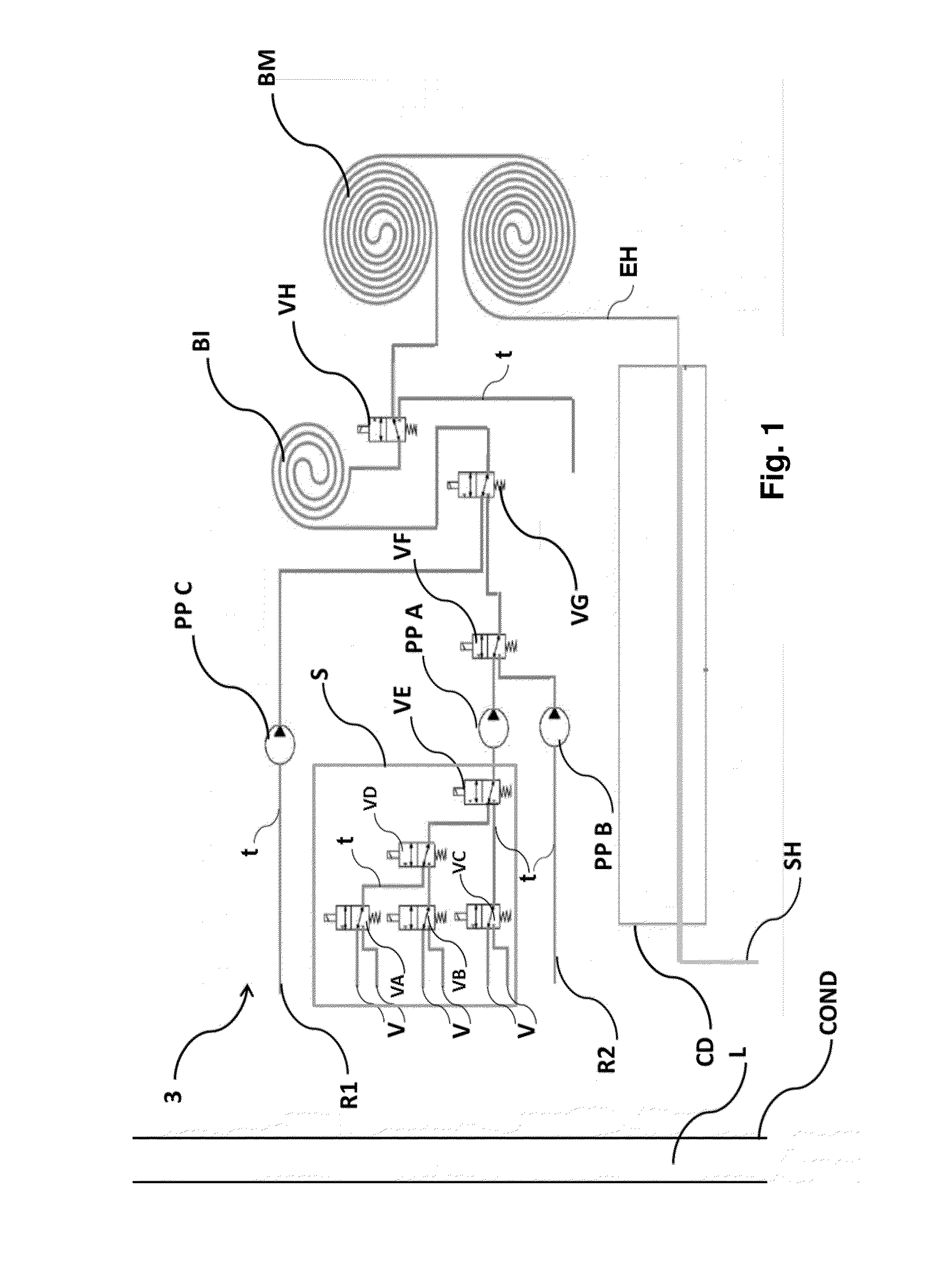
[0098]An example of an analysis device according to the present invention is represented schematically in FIG. 1.

[0099]The device comprises a leaktight analytical circuit (3) comprising a double injection loop (BI) of defined volume connected to at least one mixing loop (BM), and a turbidimetric analysis means (CD), the injection loop, the mixing loop and the analysis means may be passed through continuously by a liquid, the injection loop and the mixing loop being separated by a valve (VH).

[0100]The injection loop is a Teflon (registered trademark) tube of wound-up shape, having an internal diameter of 0.80 millimeter and a length of around 6 centimeters. The predefined volume of this injection loop makes it possible to inject a defined amount of solution for detecting sulfates owing to the peristaltic pump (PPC).

[0101]The mixing loop is also a Teflon (registered trademark) tube of wound-up shape. It has an internal diameter of 0.8...

Example

Example 2

Example of a Coastal Version Device for the Analysis of a Nanofiltered Seawater

[0122]The device from example 1 was contained in a leaktight chamber as represented in FIGS. 5a and 5b.

[0123]In FIG. 5a, which is a photograph of this coastal version device, it is observed that it is composed of a single block, with, in its upper part, the means for connecting the device to the source of nanofiltered seawater for the analysis thereof.

[0124]Seen in FIG. 5b, which is a schematic representation of the coastal device, is the connector (CAI) that enables current to be supplied to the apparatus, and also the communication between the apparatus and the software.

[0125]The hydraulic module, namely the injection loop and mixing loop according to the invention, and the electronics / optical module, namely a detection cell (DC), 3 micro-LEDs, a photodiode and an electronic detection board are contained within a leaktight chamber for underwater immersion having a height of 210 millimeters, a ...

Example

Example 3

Deep Sea Version Device for the Analysis of a Nanofiltered Seawater

[0131]The deep sea version device used according to example 3 was manufactured in accordance with the coastal version from example 2 by containing the hydraulic module and the electronics / optical module in two separate and leaktight chambers (FIG. 7a).

[0132]The leaktightness of the two modules was ensured by placing the hydraulic module at equal pressure in dielectric oil (Fluorinert (trademark) (3M, USA), FC77, 3M, density 1.78), whilst the electronics / optical module was positioned in a leaktight casing made of titanium.

[0133]A duct linked to the hydraulic module via a connector (COE) and linked to the electronics / optical module via a connector (CMH) enables the hydraulic module to be supplied with power and enables the command actions of the hydraulic module (FIG. 8).

[0134]The electronics / optical module has a connector (CAI) which enables a remote communication between the software and the device and which...


PUM


Abstract

The invention relates to an analysis device (1) comprising: a tight analytical circuit (3) comprising an injection loop (BI), at least one mixing loop (BM), and a turbidimetry analysis means (CD), a liquid being able to continuously circulate through the injection loop, the mixing loop and the analysis means; a means (IL) for injecting said liquid into said injection loop and a means for removing said liquid from a source (S); a means (ISR) for injecting, into said injection loop, a solution for displaying sulfates in said liquid by means of turbidimetry; and a means (ISP) for injecting a rinsing solution, comprising a peristaltic pump (PPB) and a system (VF, VG) of valves placed between the pump (PPB) and said injection loop. The invention is especially applicable in fields of the offshore oil industry.

Description

TECHNICAL FIELD[0001]The present invention relates to a device for analyzing the amount of sulfates contained in a liquid, and also to the use of the device for analyzing a liquid, especially seawater, especially nanofiltered seawater.[0002]The present invention especially finds applications in the fields of the offshore oil industry, especially the exploitation of deposits, for example oil deposits, and also in industrial processes such as the manufacture of paper and cellulose, the manufacture of edible oils, tanneries, environmental monitoring, water treatment, etc.[0003]In the description below, the references between brackets ([ ]) refer to the list of references presented at the end of the examples.BACKGROUND[0004]The oil industry uses various techniques for exploiting deposits, including that of injecting water into the natural reservoirs of these deposits in order to increase the pressure and thus promote the extraction of the oil. The water injected generally originates fro...

Claims


Application Information

Patent Timeline
IPC IPC(8): G01N33/18G01N21/75
CPCG01N33/18G01N21/85G01N2201/0826G01N33/182G01N2201/062G01N21/75
Inventor CARADEC, FLORIANLA S-HUON, AGATHECHATAING-PARIAUD, SOPHIEBUCAS, KARENN
Owner INSTITUT FR DE RES & DEV POUR LEXPL DE LA MER IFREMER
Why Eureka
Try Eureka