Fused Material Deposition Microwave System And Method

a microwave system and microwave technology, applied in the direction of additive manufacturing processes, manufacturing tools, coatings, etc., can solve the problems of limiting the benefits of additive manufacturing, limiting and reducing the use of additive manufacturing methods

Inactive Publication Date: 2016-08-11
ESCAPE DYNAMICS
View PDF0 Cites 29 Cited by
  • Summary
  • Abstract
  • Description
  • Claims
  • Application Information

AI Technical Summary

Benefits of technology

[0006]A fused material deposition microwave system includes a high power microwave source, at least one deposition nozzle having adjustable outlet diameter for depositing one or more materials, a waveguide for guiding microwave energy to the deposition nozzle to melt the materials, and a material source to supply one or more materials to the deposition nozzle. The system further includes a controller for controlling the deposition nozzle, microwave energy flow, and material source, according to a computer-aided manufacturing (CAM) set of instructions to deposit and fuse molten material on a workpiece.
[0007]A fused material deposition microwave method includes delivering one or more materials to a deposition nozzle, guiding microwave energy from a high power microwave source to the deposition nozzle to melt the one or more materials, and controlling the material delivery, microwave energy, and position of the deposition nozzle according to a computer-aided manufacturing (CAM) set of instructions, thereby depositing and fusing molten material into a workpiece.

Problems solved by technology

These additive manufacturing methods, however, have several drawbacks and limitations.
For example, there are trade-offs between equipment and material costs, object resolution, speed, and properties of the finished object.
These compromises are especially limiting in the case of additive manufacturing of metals and ceramics as well as large parts made of any material.
Alternatively, additive manufacturing of metals may require a multi-step process in which several long and costly steps are required, limiting the benefits of additive manufacturing.
However, laser-based 3D printing processes for metallic and ceramic parts are often slow and limited in the size of objects they can print.
Although resolution of such laser devices is high, the speed of generating the object is often slow because the laser beam is narrowly focused and has a small diameter requiring rapid movement (scanning) across each deposited layer (resulting in non-uniform heat distribution, poor fusing, and inconsistent mechanical properties between different parts).
Moreover, penetration of the laser beam into certain materials is limited, resulting in the thickness of each added layer being small.
Further, small diameter and small penetration thickness of a laser beam often can cause significant residual stress in the material leading to undesirable properties of the work piece.
Selective laser sintering methods, where a laser beam fuses layers of metal inside of powder bed, such as described in U.S. Pat. No. 4,863,538, are limited in the size of parts that can be produced because the parts are fabricated inside a large volume of metallic powder deposited layer by layer in the printing process, and hence the manufacturing process requires a very large amount of high quality uniform powder material.
For large scale objects, the amount of power required for manufacturing becomes impractical.
Other methods of applying heat during the sintering portions of additive manufacturing processes entail a number of drawbacks and limitations.
For example, sintering beams derived from frequencies around 2.45 GHz (i.e., wavelengths approximately equal to 12.22 cm) may be used; but the energy distribution of such beams can be difficult to control, with the beam being excessively diffused and unfocussed.
As a result, heat is unintentionally applied outside of intended target areas, and precise control over depths of energy penetration become impossible.

Method used


Image

  • Fused Material Deposition Microwave System And Method
  • Fused Material Deposition Microwave System And Method
  • Fused Material Deposition Microwave System And Method

Examples


Embodiment Construction

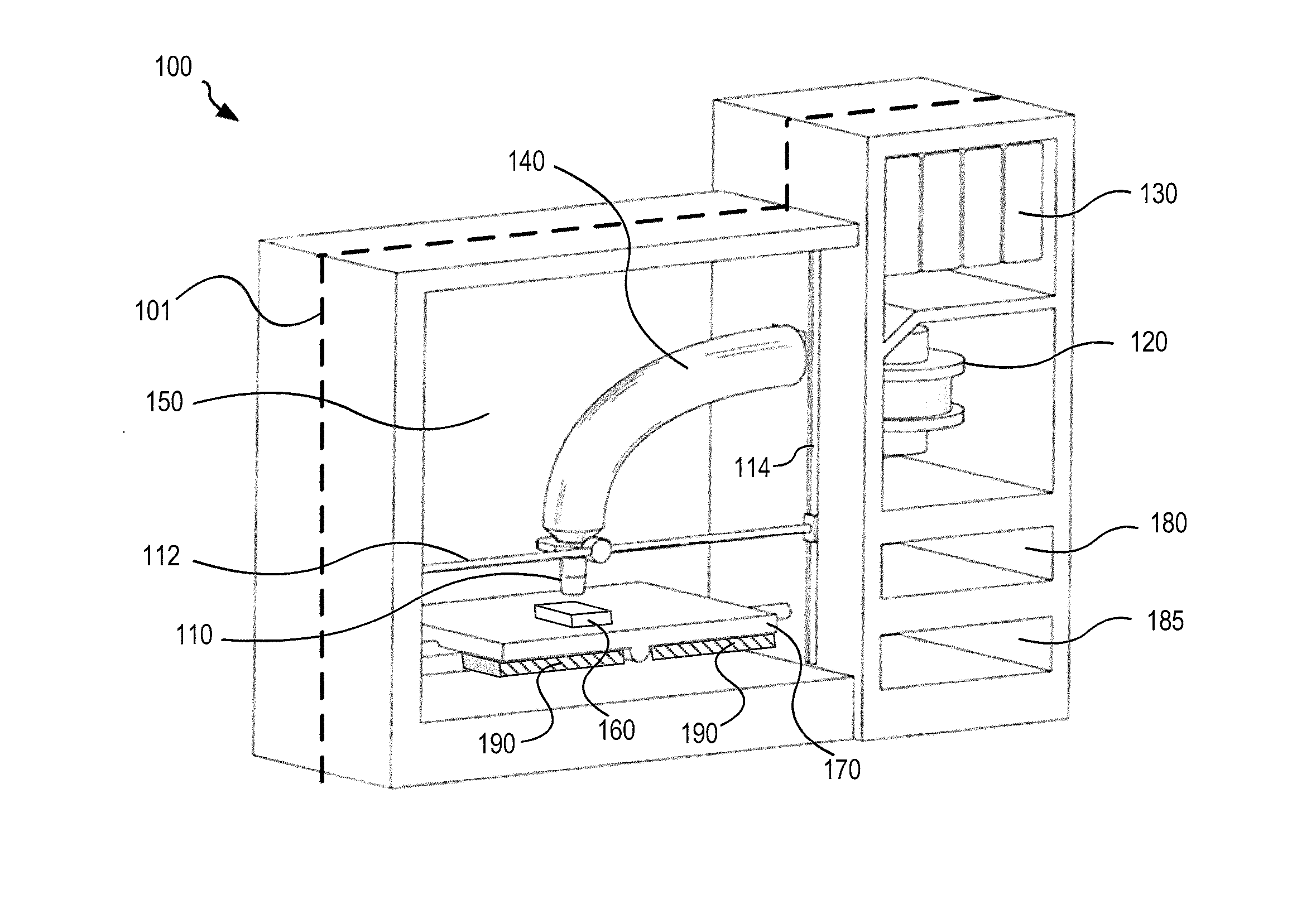
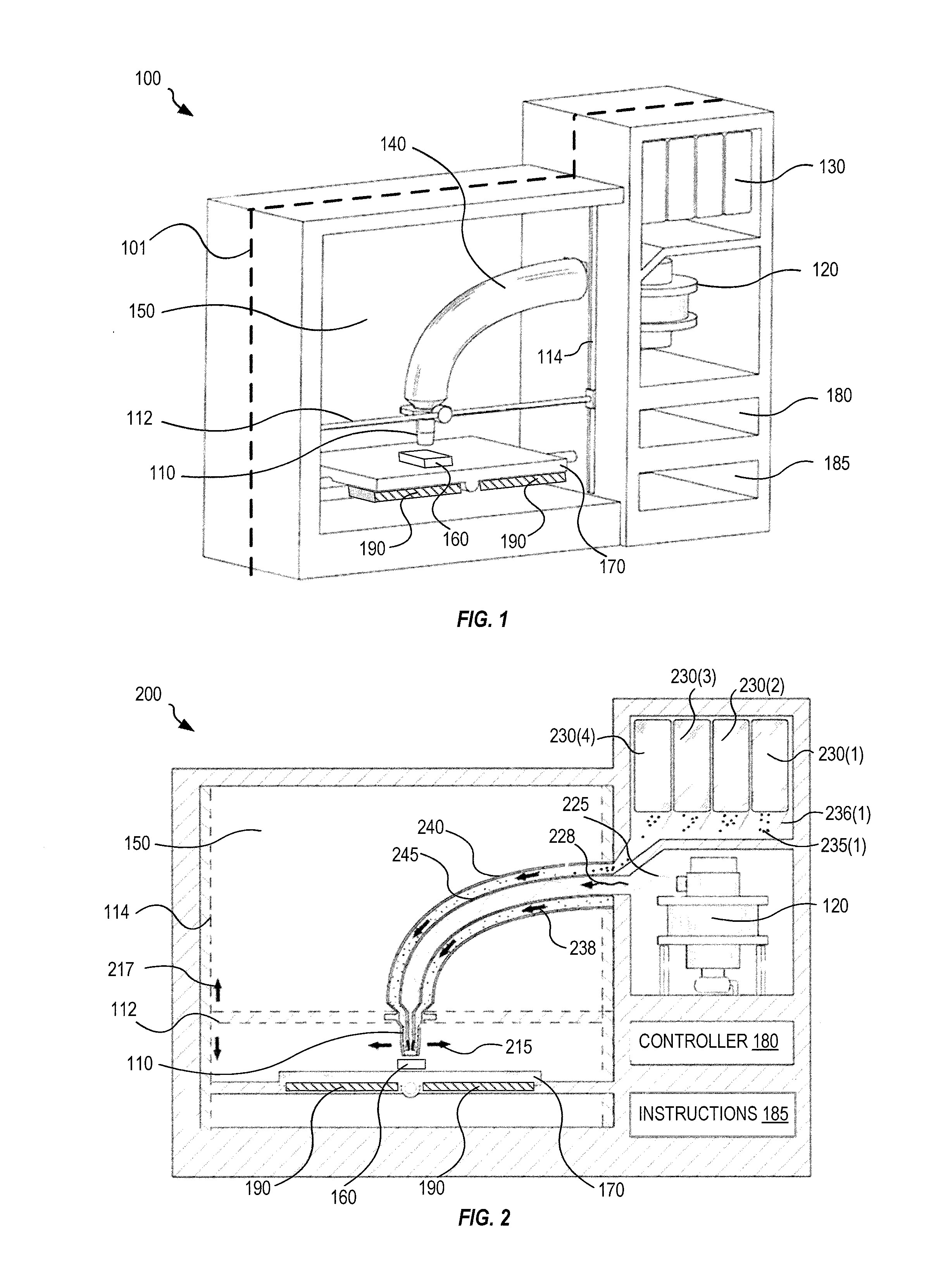
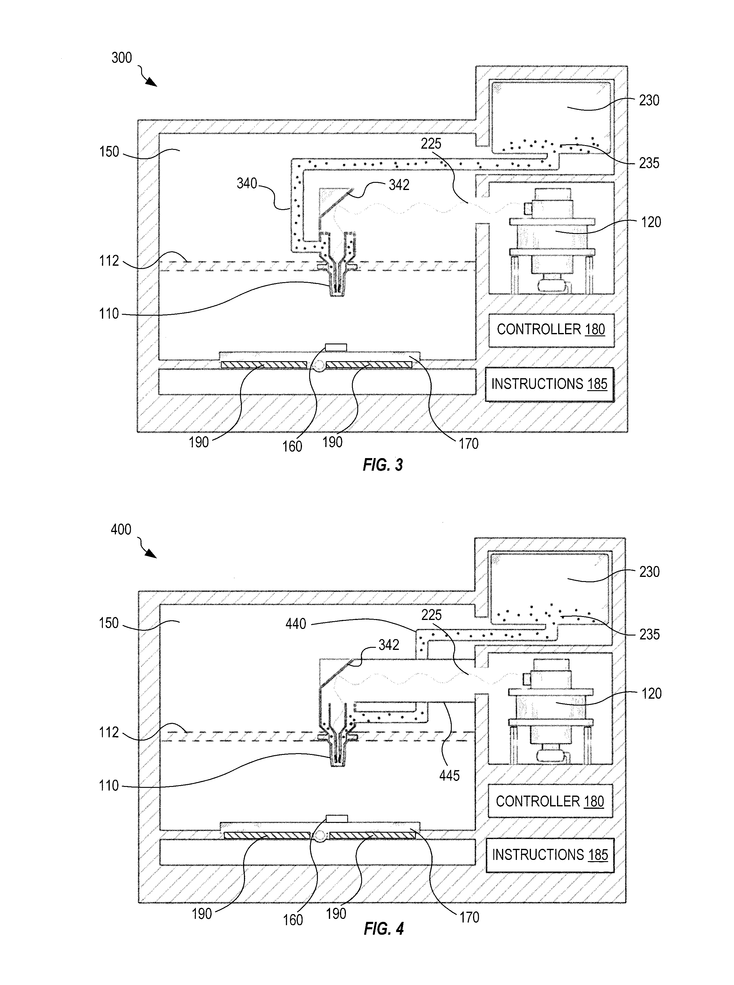
[0020]FIG. 1 shows one fused material deposition microwave system 100. System 100 includes a deposition nozzle 110 for depositing one or more materials, a microwave energy source 120 for providing microwave energy, and a material source 130 for supplying one or more materials. Examples of microwave energy source 120 include a gyrotron, klystron, magnetron, or other source of high-power microwave energy. Microwave energy source 120 is for example an integrated high-power microwave source that includes a compact power supply. Alternatively, microwave energy source 120 is modular, has an external power supply, and is coupled to a larger manufacturing apparatus. The modular embodiment is beneficial when system 100 is for example integrated into a CNC mill or a laser-based 3D printer. In an embodiment, the output power of microwave energy source 120 is adjusted by tuning current and voltage of an internal electron gun that directly affects electron current flowing inside a microwave cavi...


PUM

PropertyMeasurementUnit
wavelengthsaaaaaaaaaa
frequenciesaaaaaaaaaa
outlet diameteraaaaaaaaaa

Abstract

A fused material deposition microwave system and method include at least one high power microwave source, at least one deposition nozzle having adjustable outlet diameter for depositing one or more materials, a waveguide for guiding microwave energy to the deposition nozzle to melt the materials, and a material source to supply one or more materials to the deposition nozzle. The system and method further include a controller for controlling the deposition nozzle, microwave energy, and material source according to a computer-aided manufacturing set of instructions to deposit and fuse molten material on a workpiece. The system and method provide improvements in additive manufacturing of three-dimensional objects that are particularly beneficial for manufacturing objects made of metals and ceramics.

Description

BACKGROUND[0001]Additive manufacturing processes are used to produce three-dimensional objects. Layers of material are deposited and bonded together (optionally onto an object or a substrate) according to a prescribed pattern or design to create a 3-dimensional (3D) object. A 3D printer implements this printing process by depositing a layer of material (e.g., liquid, powder, extrusion (e.g., wire) or sheet) onto a pre-existing object or substrate and subsequently fusing, by the focused application of energy, some or all of the material to the pre-existing object or substrate according to the prescribed pattern. The process repeats to deposit and fuse multiple layers (each layer representing a cross section through the object) to form the 3D object.[0002]Existing 3D printing processes include selective laser melting (SLM), direct metal laser sintering (DMLS), selective laser sintering (SLS), fused deposition modeling (FDM), stereo-lithography (SLA), laminated object manufacturing (LO...

Claims


Application Information

Patent Timeline
Patent Type & Authority Applications(United States)
IPC IPC(8): C23C16/511C23C16/44C23C16/46C23C16/52C23C16/455
CPCC23C16/511C23C16/52C23C16/463C23C16/46C23C16/4412C23C16/45563B33Y10/00B29C64/118B29C64/106B29C35/0805B29C2035/0855
Inventor TSELIAKHOVICH, DMITRIYCHU, TAK SUMMARTINEZ, GONZALO
Owner ESCAPE DYNAMICS
Why Eureka
Try Eureka