X-ray analysis in air

Active Publication Date: 2016-08-11
OXFORD INSTR NANOTECH TOOLS
View PDF0 Cites 0 Cited by
  • Summary
  • Abstract
  • Description
  • Claims
  • Application Information

AI Technical Summary

Benefits of technology

[0016]Preferably a differential pressure element is utilised for dividing the first and second pressure environments and arranged to allow passage of each of, the electron beam to the sample, and x-rays from the sample. The differential pressure element at least permits transmission of electrons and x-rays through it which may be achieved by a combination of low interaction materials and low thickness. It is desirable for the differential pressure element to be as transparent as possible (minimising attenuation of electrons or x-rays). The differential pressure element is typically either, formed from a material which is a substantially electron and x-ray transmissive material, or, is a small physical aperture (hole). Each alternative can be thought of as an electron aperture. Thus, in use, each of, the electron beam and the generated x-rays, is caused to pass between the first and second gas pressure environments through the differential pressure element which is operative to maintain the pressure differential between the first and second gas pressure environments. Typically, the at least one x-ray sensor element is positioned upon a first side of the differential pressure element and the sample is positioned upon a second side of the differential pressure element. The element may be an “aperture” which may or may not have an electron-transparent membrane across it. The specimen surface is typically positioned closely below (more generally, adjacent) the same aperture so that the x-ray sensor has line of sight of the incident focussed electron beam spot and the active elements of the sensor subtend a large solid angle at th

Problems solved by technology

However, some specimens such as liquids and hydrated biological material will not be stable under vacuum conditions and cannot be analysed.
Furthermore, specimens that are electrically insulating may accumulate charge and the negative voltage can eventually repel the incident beam so that analysis is not possible.
However, to work at full atmospheric pressure (760 Torr) would require an aperture

Method used


Image

  • X-ray analysis in air
  • X-ray analysis in air
  • X-ray analysis in air

Examples


Example

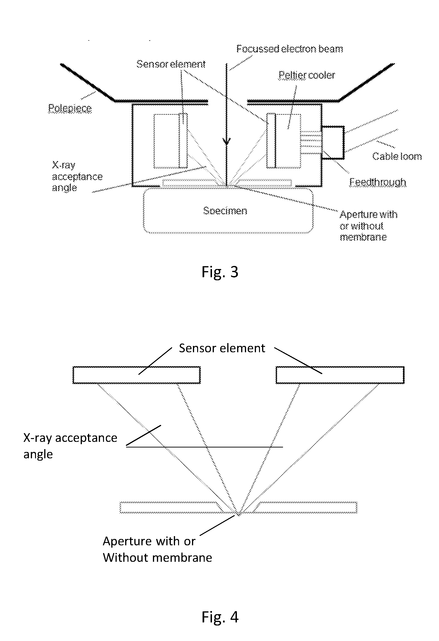
[0033]In one embodiment of the invention shown in FIG. 3, a detector module 2 is shown positioned immediately below the final lens polepiece 3 of an electron microscope 4. The x-ray sensor 5 of the detector module 2 is composed of four individual silicon drift detector (SDD) elements 6 arranged symmetrically around the central axis with their sensitive faces arranged vertically. Each element 6 is 0.5 mm thick and the front surface is 3 mm in height and 4 mm deep. Each element 6 is mounted on a Peltier cooling stack 7 and the electrical connections are taken through a feedthrough and cable loom 8 out to external electronics for controlling the cooling, electrically biasing the detector elements and sensing and measuring the signals. Peltier coolers require a heat sink and are thermally-connected to the casing of the detector module. If the specimen is in full atmosphere, the heat sink can be fins attached to the casing. Alternatively, the casing can be thermally connected to the larg...


PUM


Abstract

An x-ray analysis apparatus comprises an electron beam assembly for generating a focused electron beam within a first gas pressure environment. A sample assembly is used for retaining a sample within a second gas pressure environment such that the sample receives the electron beam from the electron beam assembly and such that the gas pressure in the second gas pressure environment is greater than the gas pressure within the first gas pressure environment. An x-ray detector is positioned so as to have at least one x-ray sensor element within the first gas pressure environment. The sensor element is mounted to a part of the electron beam assembly which is proximal to the sample assembly and further arranged in use to receive x-rays generated by the interaction between the electron beam and the sample.

Description

FIELD OF INVENTION[0001]The present invention relates to an apparatus and method for x-ray analysis, particularly that enables x-ray elemental analysis of specimens at partial or full atmospheric pressure at high spatial resolution using a focussed electron beam.BACKGROUND TO THE INVENTION[0002]With reference to FIG. 1, for x-ray analysis in an electron microscope (EM) 100, an x-ray spectrum is measured by sensing and measuring the energies of individual x-ray photons emitted by a specimen 101 when it is hit by a focussed electron beam 102. (Note that in this document, the convention is that the electron beam travels vertically downwards towards the specimen and this is the context for words such as “below” and “above”. In practice the electron beam can be oriented in any direction, including vertically upwards.) Each x-ray photon is an energetic particle and the energy is typically converted into charge using a solid state detector 105. The charge is measured so that a count can be...

Claims


Application Information

Patent Timeline
IPC IPC(8): H01J37/244H01J37/28
CPCH01J37/244H01J37/28H01J2237/164H01J2237/182H01J2237/24415H01J2237/2445H01J2237/2608H01J2237/188
Inventor STATHAM, PETER
Owner OXFORD INSTR NANOTECH TOOLS
Why Eureka
Try Eureka