

Polarizing plate, method for manufacturing same, and image display device comprising same
a technology of polarizing plate and manufacturing method, which is applied in the direction of polarizing elements, instruments, other domestic objects, etc., can solve the problems of difficult to maintain the thickness of the protective film at 20 m or less, difficult to secure a uniform degree of curing, and thinness of the liquid crystal device, etc., to achieve excellent water resistance and reduce the generation rate. , the effect of reducing the thickness
- Summary
- Abstract
- Description
- Claims
- Application Information
AI Technical Summary
Benefits of technology
Problems solved by technology
Method used
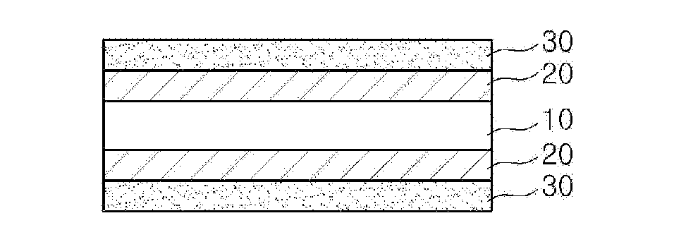
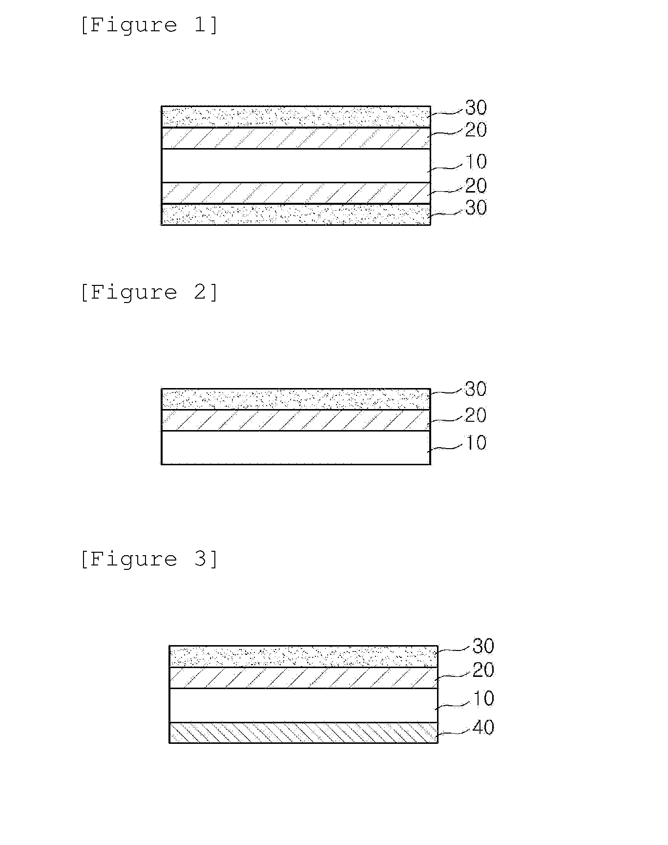
Image

Examples
preparation example 1
Manufacture of Acrylic Protective Film
[0124]A raw material pellet was manufactured by supplying a resin composition, in which poly(N-cyclohexylmaleimide-co-methylmethacrylate), a styrene-maleic anhydride copolymer resin and a phenoxy-based resin were uniformly mixed with each other at a weight ratio of 100:2.5:5, to a 24Φ extruder in which a portion from a raw material hopper to the extruder was substituted with nitrogen, and melting the mixed resin composition at 250° C.
[0125]PKFE (Mw=60,000, Mn=16,000, Tg=95° C.) manufactured by InChemRez® Co., Ltd., was used as the phenoxy-based resin, Dylaeck 332 with a content of 85 wt % of styrene and 15 wt % of anhydrous maleic anhydride was used as the styrene-maleic anhydride copolymer resin, and as the poly(N-cyclohexylmaleimide-co-methylmethacrylate) resin, a resin with a content of 6.5 wt % of N-cyclohexylmaleimide as a result of NMR analysis was used.
[0126]The obtained raw material pellet was dried under vacuum, melted by the extruder a...
preparation example 2
Preparation of Composition for Protective Film
[0128](1) Radical Curable Composition A
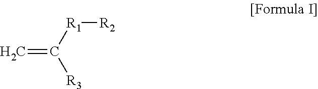
[0129]Composition A for a protective film was prepared by mixing 3 parts by weight of Irgacure 819 (radical initiator) with 67 parts by weight of 2-hydroxyethyl acrylate (Formula 1), 20 parts by weight of a carboxylated BPA-type dimethacrylate (Formula 15), and 10 parts by weight of itaconic acid (Formula 27), and then stirring the mixture at 60° C. for 4 hours.
[0130](2) Radical Curable Composition B
[0131]Composition B for a protective film was prepared by mixing 3 parts by weight of Irgacure 819 (radical initiator) with 67 parts by weight of 4-hydroxybutyl acrylate (Formula 5), 20 parts by weight of a carboxylated BPA-type dimethacrylate (Formula 15), and 10 parts by weight of itaconic acid (Formula 27), and then stirring the mixture at 60° C. for 4 hours.
[0132](3) Radical Curable Composition C
[0133]Composition C for a protective film was prepared by mixing 3 parts by weight of Irgacure 819 (radica...
experimental example 1
Measurement of Average Functional Group Equivalent Weight
[0138]The average functional group equivalent weights of Compositions A to E for a protective film were measured by the aforementioned calculation method, and are shown in the following [Table 1].
PUM
| Property | Measurement | Unit |
|---|---|---|
| curing shrinkage ratio | aaaaa | aaaaa |
| thickness | aaaaa | aaaaa |
| thickness | aaaaa | aaaaa |
Abstract
Description
Claims
Application Information