Method for reconstructing a 3D image from 2d x-ray images

a 3d image and image technology, applied in the field of medical x-ray imaging systems, can solve the problems of device prone to mechanical distortion, device in general not usable inside the operating room, and mechanical rigidity insufficient to reproduce the desired projection geometry along a chosen path with sufficient accuracy, so as to improve the reconstruction quality of a 3d image

Active Publication Date: 2016-08-25
ECENTIAL ROBOTICS
View PDF8 Cites 60 Cited by
  • Summary
  • Abstract
  • Description
  • Claims
  • Application Information

AI Technical Summary

Benefits of technology

[0035]The present invention provides a method for improving the reconstruction quality of a 3D image, especially in relation with mobile X-ray imaging systems used for intra-operative 3D imaging in orthopedics, traumatology and other surgical or diagnostic fields.

Problems solved by technology

While computer tomography is a well-established class of stationary X-ray imaging systems used for 3D reconstruction in a radiology department, these devices are in general not usable inside the operating room.
However, while very well adapted to intra-operative 2D imaging tasks thanks to their maneuverability, C-arms, originally not designed for 3D imaging, are mechanically not sufficiently rigid to reproduce the desired projection geometry along a chosen path with sufficient accuracy due to their open gantry design.
The open gantry design makes the device prone to mechanical distortions such as bending depending on the current position / orientation.
In particular, mobile C-arms are prone to collisions with doors or other objects while moved around, resulting in non-elastic deformations of the C-arm.
Depending on the type of bearing and drive of the C-arm, wobbling of the C-arm cannot be avoided due to its own mass and the masses of the x-ray source and x-ray detector altering the nominal trajectory thus leading, as a geometry error, to limitation of the spatial resolution of the reconstructed 3D image.
On the other hand, irreproducible deviations of the projection geometry like thermal shifts, fatigue over time, mechanical deformations due to collisions of the device during use or transport cannot be compensated for.
Since deviations can only be detected during the offline calibration, there is a risk that at one point in time, between two recurring offline calibrations, the 3D images will lack the accuracy necessary for clinical use.
Another drawback of offline calibration methods is to restrict the use of the C-arm for 3D reconstruction to only one trajectory, i.e. the one that has been calibrated.
One of the general problems with such an online calibration method based on radiopaque markers aiming at a full calibration, i.e. determining the complete projection geometry for each acquired image, is the fact that for diagnostic imaging, the C-arm is positioned such that the anatomical region of interest (ROI) is visible on each image.
Since the phantom can obviously not be placed exactly in the same position, it is usually difficult—if not impossible—to ensure the visibility of the phantom in all images, thus often not allowing a full calibration.
Another problem is that radiopaque or very radio-dense objects such as metal parts of the operating table, surgical instruments, implants etc. may occlude one or more of the phantom markers in one or more of the images.
However, while providing potentially good calibration accuracy, this phantom significantly obstructs the surgical access to the patient and is very cumbersome and expensive to manufacture and maintain with high mechanical accuracy.
The marker ring required in this method complicates the access to the patient and must be repositioned each time the C-arm position or orientation is adjusted.
This system is prone to occlusion and magnetic field distortion problems as well as ergonomic restriction preventing these systems from being used in a clinical environment.
This method is complex to manage and maintain with a high degree of accuracy over time, and it cannot recover the full projection geometry and captures only some deformations.
While this method could in theory be effective, it is not revealed how image features to be tracked in sinograms are identified.
No method for detecting such natural features with a high degree of precision and reproducibility is described, which makes it non-usable in reality.

Method used


Image

  • Method for reconstructing a 3D image from 2d x-ray images
  • Method for reconstructing a 3D image from 2d x-ray images
  • Method for reconstructing a 3D image from 2d x-ray images

Examples


Embodiment Construction

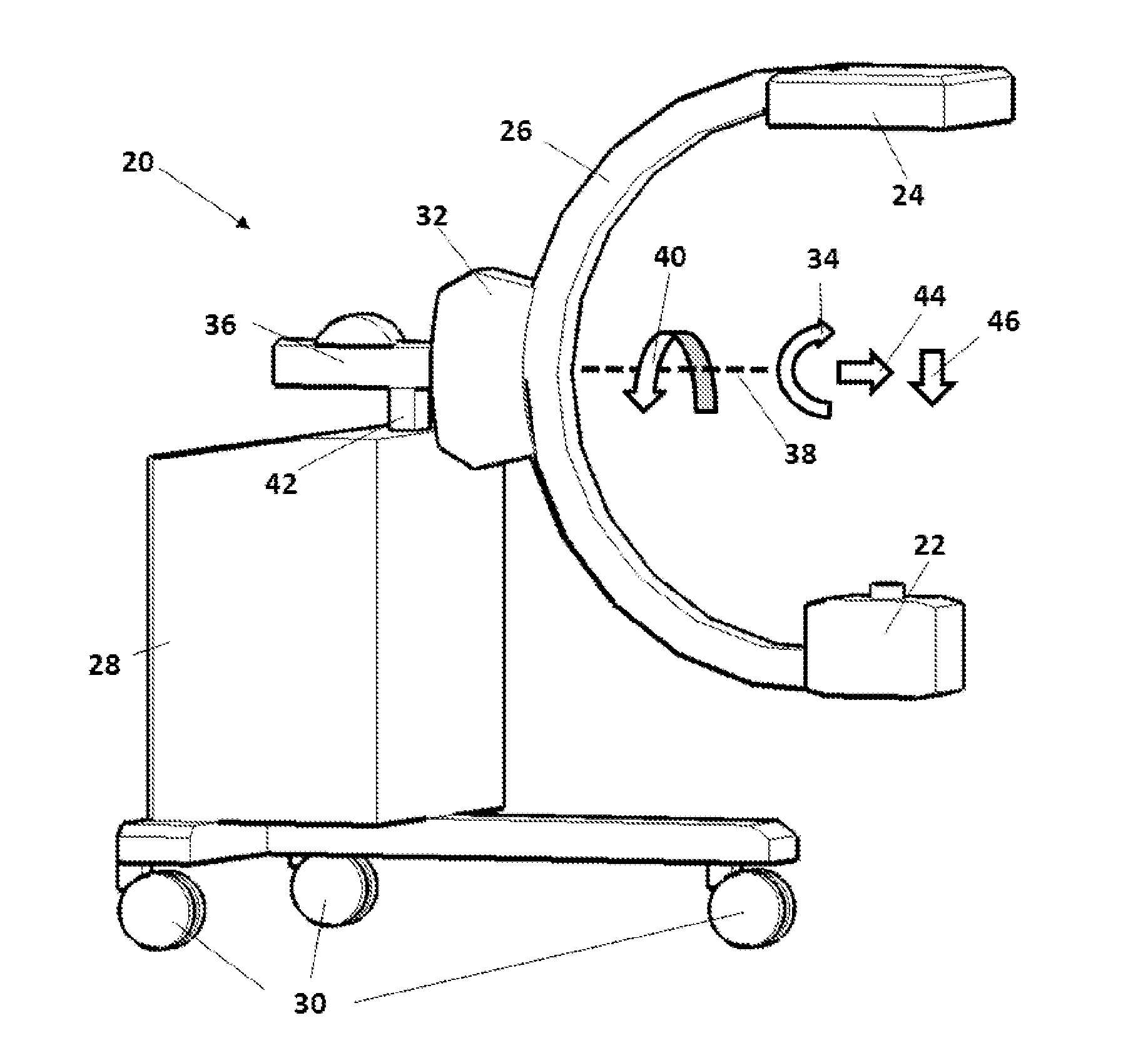
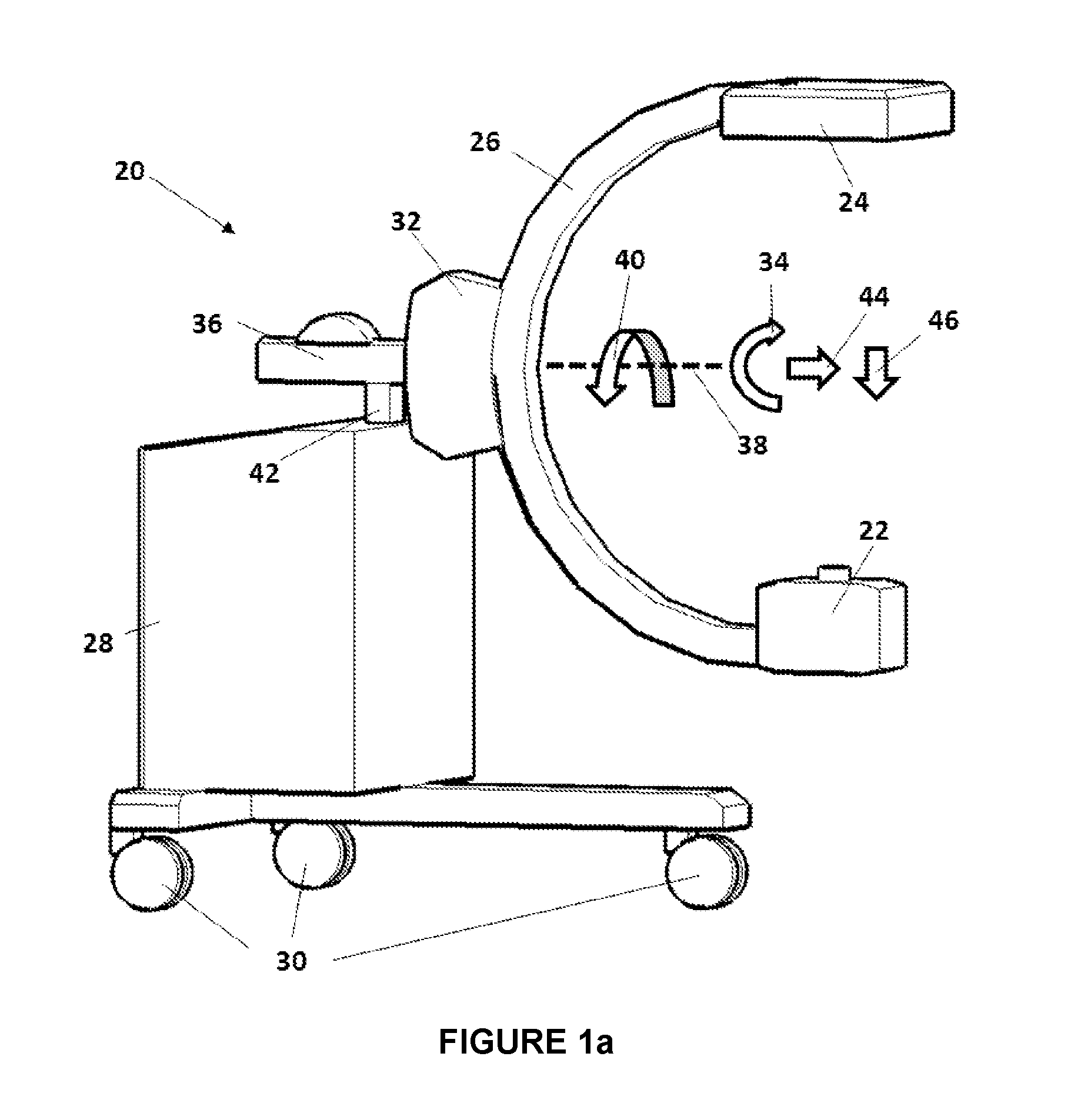
[0088]FIG. 1a depicts one embodiment of a mobile X-ray imaging system 20 comprising an X-ray source 22, an X-ray detector 24, a C-shaped arm 26, and a chassis 28 with attached rollers 30.

[0089]The X-ray source 22 is attached at one end of C-shaped arm 26 and the X-ray detector 24 is attached at the other end of C-shaped arm 26.

[0090]The X-ray source 22 and the detector 24 are mounted facing each other on opposing ends of the C-shaped arm 26 in a manner known in the art.

[0091]The 2D images captured by detector 24 can be transmitted to a graphic display not shown in the figure for direct visualization.

[0092]The 2D images may also be stored in a memory of a data processing unit of the X-ray imaging system.

[0093]Said data processing unit (not illustrated) typically comprises a processor that is adapted in particular to compute a 3D image from a set of acquired 2D images, to compute transformations between different coordinate systems, etc.

[0094]The data processing unit further comprises...


PUM


Abstract

The present invention relates to a method for reconstructing a 3D image from 2D X-ray images acquired with an X-ray imaging system, said method comprising the steps of:
    • a) receiving a set of 2D X-ray images of a region of a patient with said X-ray imaging system,
    • b) computing an initial 3D image within the coordinate system of the X-ray imaging system by using at least part of said 2D X-ray images with their respective projective geometry data;
    • c) projecting said initial 3D image on at least part of said 2D X-ray images and adjusting the respective projective geometry data of said images, said adjustment comprising registration of said images with the projection of the initial 3D image using an image-to-image registration technique;
    • d) computing an updated 3D image using the complete set of 2D X-ray images with their respective adjusted projective geometry data.

Description

FIELD OF THE INVENTION[0001]This invention generally relates to medical X-ray imaging systems, specifically to methods and devices for improving the quality of 3D images reconstructed from a set of 2D projection images.BACKGROUND OF THE INVENTION[0002]X-Ray imaging systems are frequently used during medical surgical procedures and interventions to provide physicians with image based information about the anatomical situation and / or the position and orientation of surgical instruments.[0003]These devices typically provide two-dimensional projection images with different structures superimposed along the path of the X-rays.[0004]A typical example of such a device for use in an intra-operative setting is the so-called C-arm used in a mobile or stationary manner and essentially consisting of a base frame on which a C-shaped arm is attached with several intermediate joints allowing moving the C-shaped arm in space along several degrees of freedom.[0005]One end of the C-shaped arm carries...

Claims


Application Information

Patent Timeline
Patent Type & Authority Applications(United States)
IPC IPC(8): A61B6/00A61B6/03A61B90/00
CPCA61B6/032A61B6/4441A61B6/5205A61B6/584A61B6/5235G06T2211/424A61B90/39A61B2090/3966G06T11/006A61B6/4405A61B6/0407G06T7/0012G06T2207/10116G06T2207/20048
Inventor LAVALLEE, STEPHANEFLEUTE, MARKUSVAN BEEK, LAURENCE
Owner ECENTIAL ROBOTICS
Why Eureka
Try Eureka