Amphibious Flying Car

Active Publication Date: 2016-08-25
HU XINRU
View PDF0 Cites 22 Cited by
  • Summary
  • Abstract
  • Description
  • Claims
  • Application Information

AI Technical Summary

Benefits of technology

The present invention provides an amphibious flying car that can quickly switch between water sailing, land traveling, and sky flying. The car uses existing technologies from cars, ships, and aircrafts to overcome problems caused by differences in technologies. It is safe, efficient, practical, and artistic. The car employs carbon fiber reinforced composites and light alloy components to maximize effective power and stability in different environments. The strake wing and top provide stability for water and sea area traveling, while the folded rotor wing and upper airfoil enable land and off-road vehicle traveling. The car can reach specific destinations quickly and improve delivery efficiency.

Problems solved by technology

Existing vehicles mostly can only work in one kind of working area; for example, a car can only travel on the land, a plane can only fly in the sky, and a ship can only sail on the water.
Even some triphibious vehicles have been proposed, which however have some limitations; for example, they need a runway to take off and land, their trafficability on land is poor, and their speed when sailing on the water is slow, and so on.
Nowadays, when dealing with emergencies and disasters and defending the homeland, protecting the human life, property and homeland security has become more and more important; unfortunately, in case of natural disasters and emergencies, no existing vehicle can be a qualified transport vehicle that meets all the demands.
Since these main factors bring out technical difficulties that have mutual restrictions, a practical amphibious flying transport vehicle that can be used in every day life is still absent.

Method used


Image

  • Amphibious Flying Car
  • Amphibious Flying Car
  • Amphibious Flying Car

Examples


Embodiment Construction

[0024]In the following, the present invention will be explained in more detail in combination with the Figures.

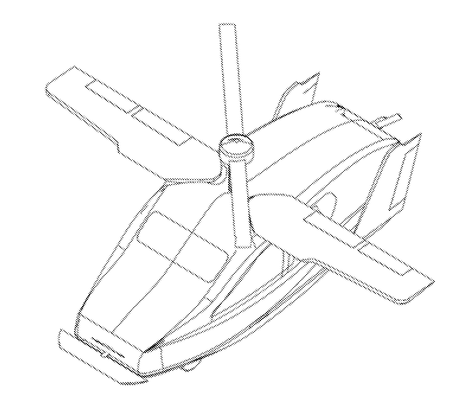
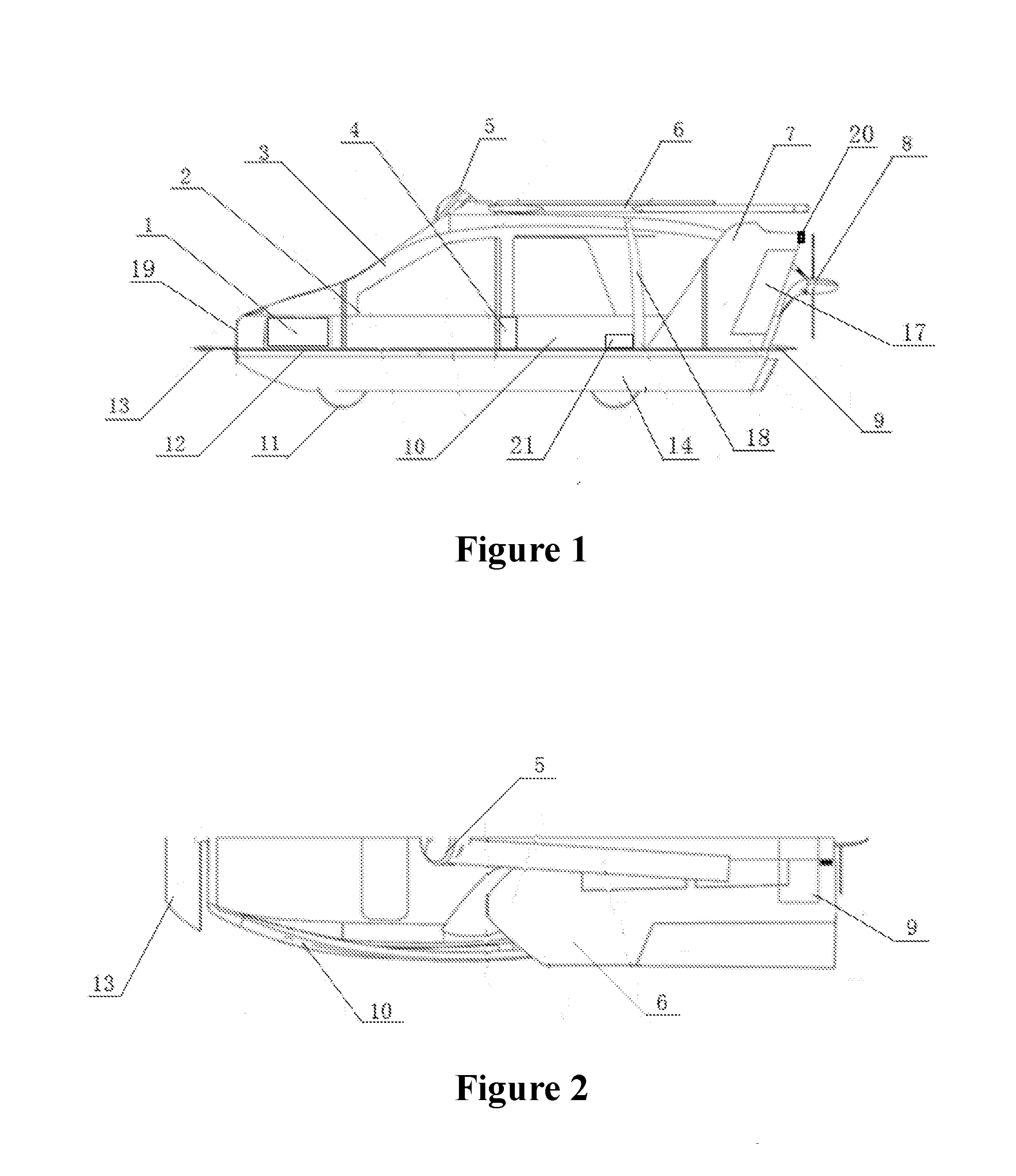
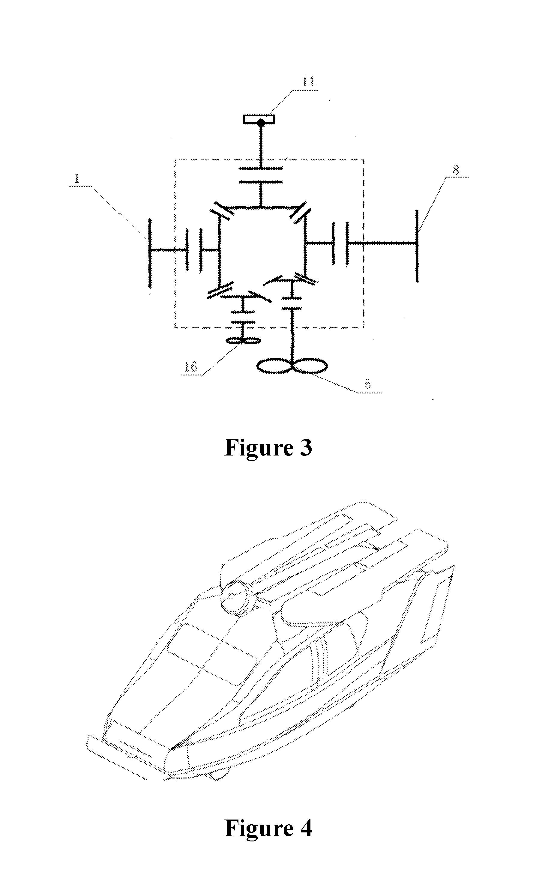
[0025]As shown in FIGS. 1, 2 and 3, the present invention provides an amphibious flying car, which comprises a casing 3, a chassis 12, a ship bottom body 14, a vehicle wheel 11, a drive system and the operating system 2; wherein the casing 3 is fixedly arranged on the chassis 12; an upper airfoil 6 and a rotor wing 5, which are arranged on the top of the casing 3, are fixed on a bearing carrier located at the orthocenter of the fuselage; the upper airfoil 6 is hinged to the casing 3 via a hinged shaft; the chassis 12 is connected with the ship bottom body 14; a strake wing 10 is provided at the position where the casing 3, the chassis 12 and the ship bottom body 14 are combined; the horizontal wing comprises a stabilizing plane 13 and an elevator 9, which are respectively located at the front end and the rear end of the fuselage; the vertical twin fins 7 are arranged at bot...


PUM

PropertyMeasurementUnit
Angleaaaaaaaaaa

Abstract

The present invention provides an amphibious flying car, comprising: a casing, a chassis, a ship bottom body, a vehicle wheel, a drive system and an operating system; an upper airfoil and a rotor wing which are arranged on the top of the casing, are fixed on a bearing carrier located at the orthocenter of the fuselage; a strake wing is provided at the position where the casing, the chassis and the ship bottom body are combined; the horizontal wing comprises a stabilizing plane and an elevator, which are respectively located at the front end and the rear end of the fuselage; the vertical twin fins are arranged at both sides of the rear end of the fuselage, and its root segments are fixedly connected to the strake wing.

Description

FIELD OF THE INVENTION[0001]The present invention relates to the technical field of transportation means, and specifically to a transport vehicle that can travel on the land, on the water and in the sky.DESCRIPTION OF THE RELATED ART[0002]Existing vehicles mostly can only work in one kind of working area; for example, a car can only travel on the land, a plane can only fly in the sky, and a ship can only sail on the water. With the development of the technology, amphibious vehicle has been widely used in a variety of applications due to its versatility. Even some triphibious vehicles have been proposed, which however have some limitations; for example, they need a runway to take off and land, their trafficability on land is poor, and their speed when sailing on the water is slow, and so on. Nowadays, when dealing with emergencies and disasters and defending the homeland, protecting the human life, property and homeland security has become more and more important; unfortunately, in c...

Claims


Application Information

Patent Timeline
IPC IPC(8): B60F5/02B63B5/24B63H5/07B64D41/00B64C27/26B64C27/52B64C3/56B64D27/04B60F3/00B64C37/00
CPCB60F5/02B64D27/04B64C37/00B64C27/52B64C27/26B64C3/56B63H5/07B63B2005/245B63B5/24B60F3/003B64D41/00B64C27/30B64C27/50B64C35/008B64D27/08B64C2001/0072B63H25/06B63H23/02Y02T50/10Y02T50/40
Inventor HU, XINRU
Owner HU XINRU
Why Eureka
Try Eureka