Methods and systems for humidity determination via an oxygen sensor

Active Publication Date: 2016-08-25
FORD GLOBAL TECH LLC
View PDF11 Cites 6 Cited by
  • Summary
  • Abstract
  • Description
  • Claims
  • Application Information

AI Technical Summary

Benefits of technology

[0003]However, the inventors have recognized that operating the oxygen sensor in the variable voltage mode may reduce the durability of the oxygen sensor. Specifically, operating the oxygen sensor at the higher second voltage may degrade the sensor, thereby reducing the longevity of the oxygen sensor. Operating the oxygen sensor in the variable voltage mode more frequently may increase a rate of degradation of the oxygen sensor.
[0004]In one example, the above issues may be addressed by a method for: applying to an oxygen sensor a lower first reference voltage to generate a first output and a higher second reference voltage to generate a second output during a first condition; applying the first reference voltage to the oxygen sensor to generate a third output during a second condition; and adjusting engine operation based on ambient humidity estimated based on the first, second, and third output. In this way, the oxygen sensor may only be operated in variable voltage mode during the first condition and oxygen sensor durability may be increased.
[0005]In one example, during selected conditions, the oxygen sensor is operated to determine an oxygen sensor reading corrected for dry air conditions. For example, during conditions when purge and crankcase ventilation gases are not ingested in an engine intake manifold, the reference voltage of an intake oxygen sensor may be modulated. Alternatively, in embodiments where the oxygen sensor is an exhaust oxygen sensor, the selected conditions may include engine non-fueling conditions, such as a deceleration fuel shut-off (DFSO) event. Specifically, the reference voltage of the oxygen sensor m

Problems solved by technology

It may take a long time for the exhaust flow to be devoid of hydrocarbons during the engine non-fueling conditions, however, and, as such, an accurate indication of ambient humidity may be delayed.
However, the inventors have recognized that operating the oxygen sensor in the variable voltage mode may reduce the durability of the oxygen sensor.
Specifically, op

Method used


Image

  • Methods and systems for humidity determination via an oxygen sensor
  • Methods and systems for humidity determination via an oxygen sensor
  • Methods and systems for humidity determination via an oxygen sensor

Examples


Embodiment Construction

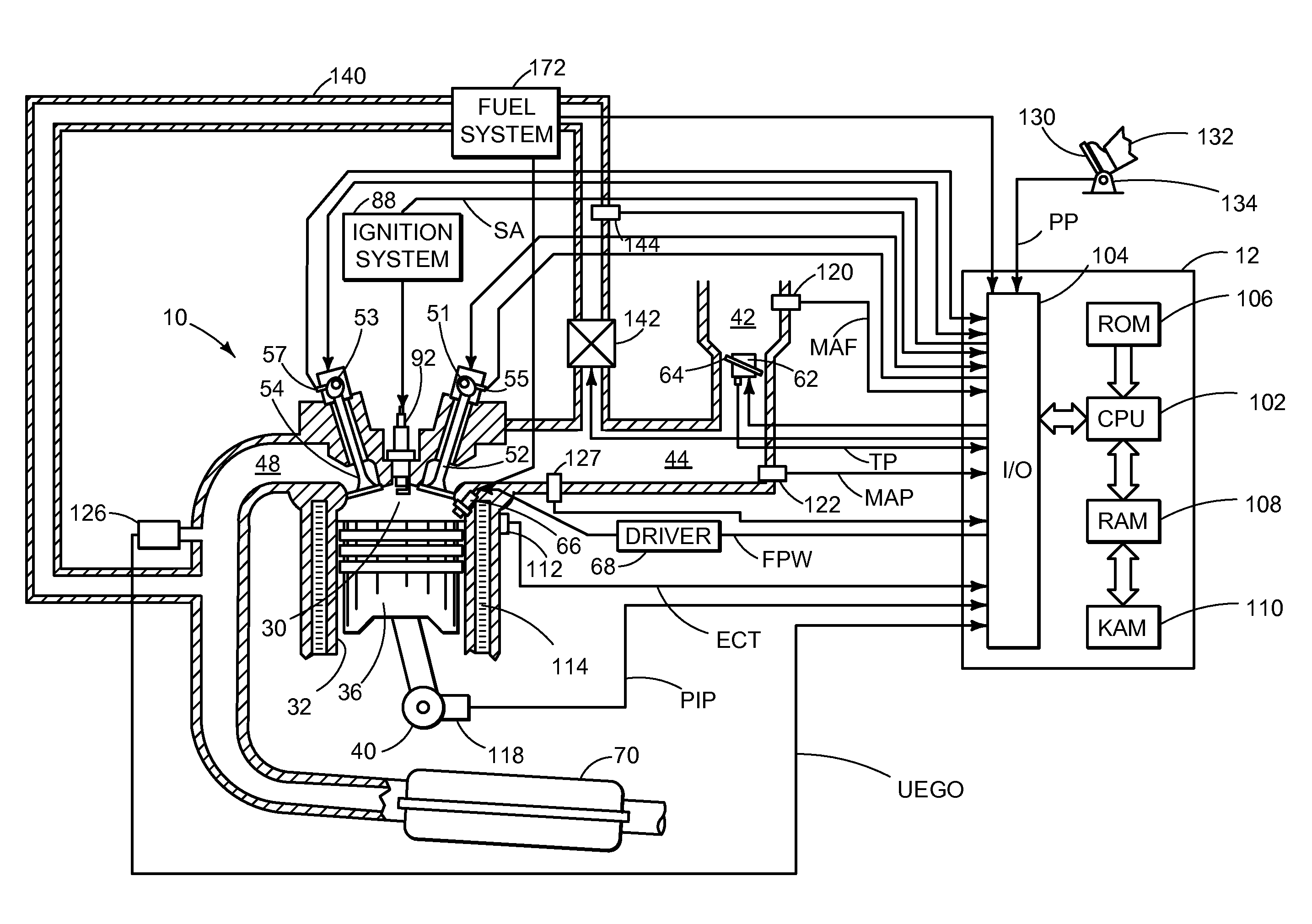
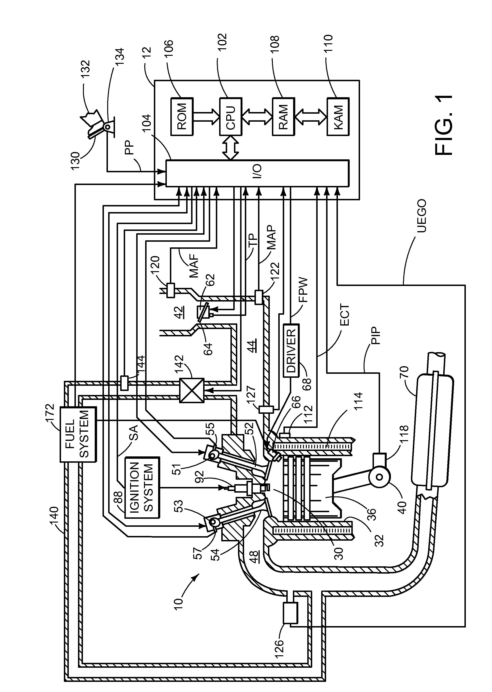
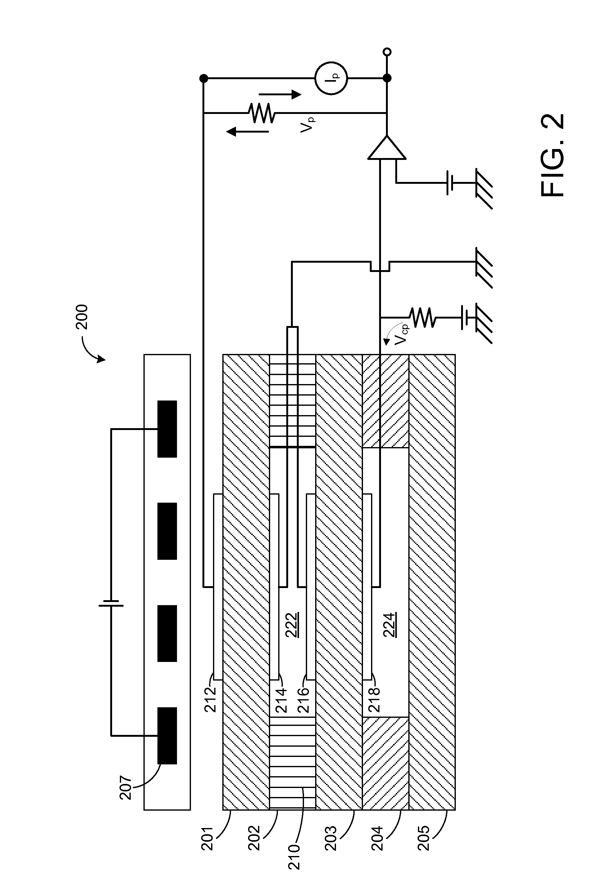
[0012]The following description relates to a method for determining ambient humidity based on outputs from an intake air or exhaust gas sensor, such as an oxygen sensor as shown in FIGS. 1-2. For example, as shown in FIG. 3, the sensor may be operated a first, lower voltage to obtain a first output which indicates a humid air oxygen reading. The sensor may then be operated at a second, higher voltage to obtain a second output which indicates a humid air oxygen reading wherein all the humidity in the air has dissociated at the oxygen sensor. A middle voltage between the first, lower voltage and the second, higher voltage may produce an oxygen sensor output indicative of a dry air oxygen reading wherein partial dissociation of the humidity occurs, as illustrated in FIG. 4. A dry air oxygen reading may then be estimated by a ratio between the first output and the second output. In this way, the dry air oxygen reading may be determined by operating the oxygen sensor in a variable voltag...


PUM


Abstract

Methods are provided for determining ambient humidity based on outputs from an intake air or exhaust gas sensor. In one example, an oxygen sensor may be operated as a variable voltage sensor, between a lower first voltage and a higher second voltage, to determine a dry air oxygen reading. Ambient humidity may then be determined based on the dry air oxygen reading and a third output of the oxygen sensor when operated at the lower first voltage and not in variable voltage mode.

Description

TECHNICAL FIELD[0001]The present application relates generally to estimating ambient humidity with an oxygen sensor of an internal combustion engine.BACKGROUND AND SUMMARY[0002]During engine non-fueling conditions in which at least one intake valve and one exhaust valve are operating, such as deceleration fuel shut off (DFSO), ambient air may flow through engine cylinders and into the exhaust system. In some examples, an exhaust gas sensor may be utilized to determine ambient humidity during the engine non-fueling conditions. It may take a long time for the exhaust flow to be devoid of hydrocarbons during the engine non-fueling conditions, however, and, as such, an accurate indication of ambient humidity may be delayed. In one example, as shown in US 2014 / 0202135, an indication of ambient humidity may be determined based on a change in pumping current output by the oxygen sensor while modulating a reference voltage of the oxygen sensor between a lower first voltage (e.g., base volta...

Claims


Application Information

Patent Timeline
IPC IPC(8): F02D41/00G01N19/10G01M15/10
CPCF02D41/0007G01N19/10G01M15/104F02D41/123F02D41/144F02D41/1454F02D2041/1472F02D2200/0418F02D41/0065F02D41/1456G01N27/4074G01N27/419
Inventor SURNILLA, GOPICHANDRAMAKLED, DANIEL A.SOLTIS, RICHARD E.
Owner FORD GLOBAL TECH LLC
Why Eureka
Try Eureka