Aircraft Water Tank

Inactive Publication Date: 2016-09-08
YOKOHAMA RUBBER CO LTD
View PDF2 Cites 12 Cited by
  • Summary
  • Abstract
  • Description
  • Claims
  • Application Information

AI Technical Summary

Benefits of technology

This patent relates to a new technology for making mouthpieces for aircraft water tanks. The technology involves using fiber-reinforced resin layers that have a uniform tension curved surface shape, which allows for the dome sections to be shaped without creating gaps between them. This improvement also increases the elasticity of the mouthpieces and reduces stress near the outer circumferential ends, which eliminates the need for a reinforcing member. This reduces the number of parts and steps needed to manufacture the aircraft water tank, resulting in lower costs and improved production efficiency.

Problems solved by technology

This increases the number of parts making up the aircraft water tank, leading to a problematic increase in the manufacturing cost of the aircraft water tank.
The aircraft water tank according to the conventional art also presents the problem that the manufacturing process is complicated by the process of adding the reinforcing members.

Method used


Image

  • Aircraft Water Tank
  • Aircraft Water Tank
  • Aircraft Water Tank

Examples


first embodiment

[0021]Next, embodiments of the present technology will be described with reference to the drawings.

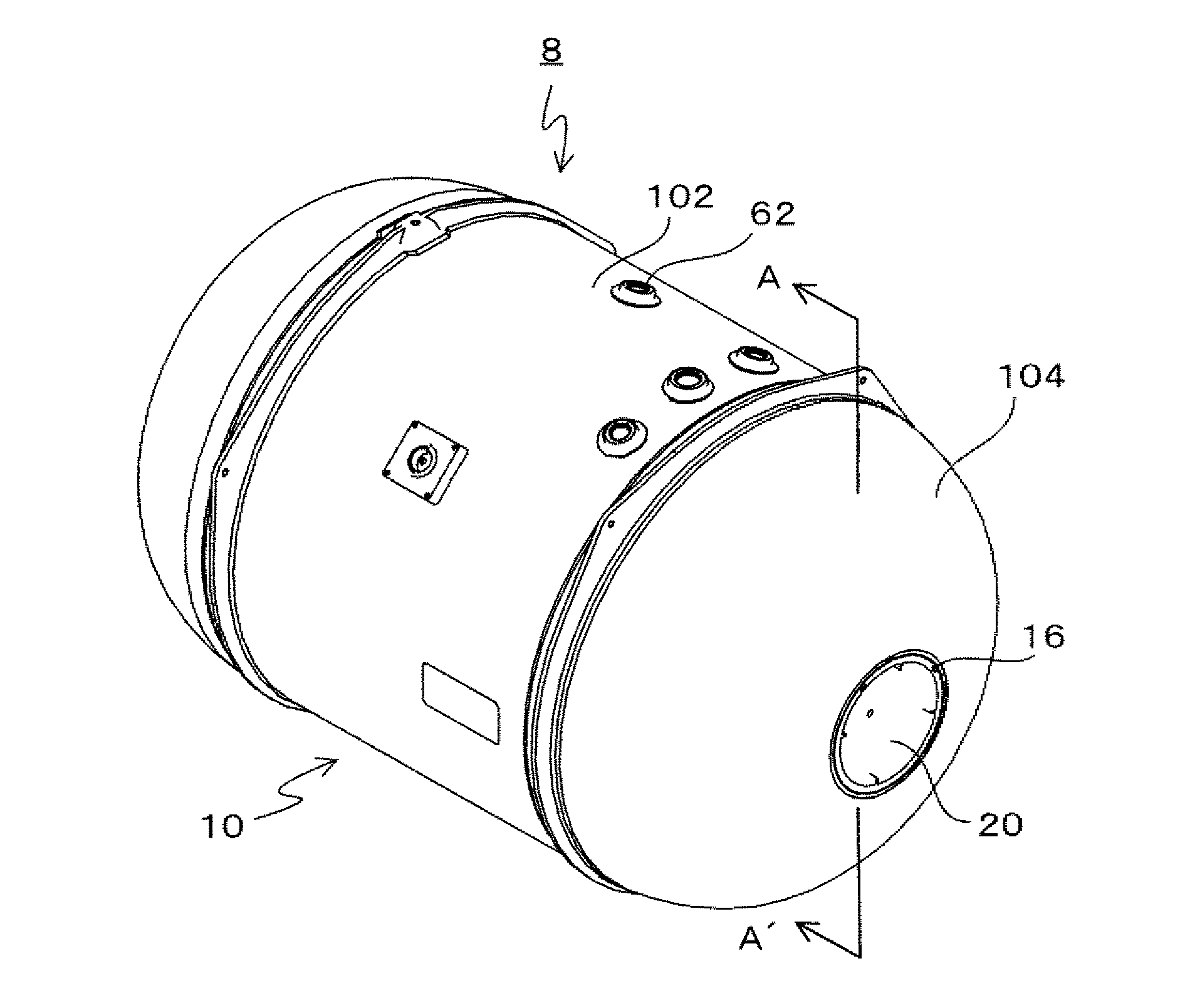
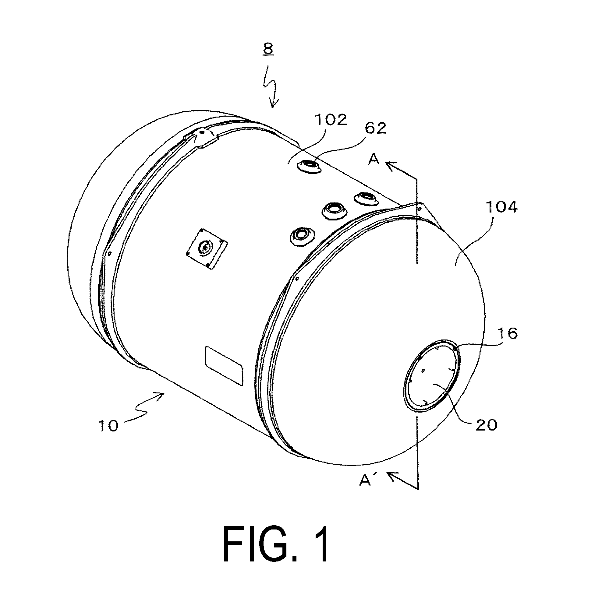
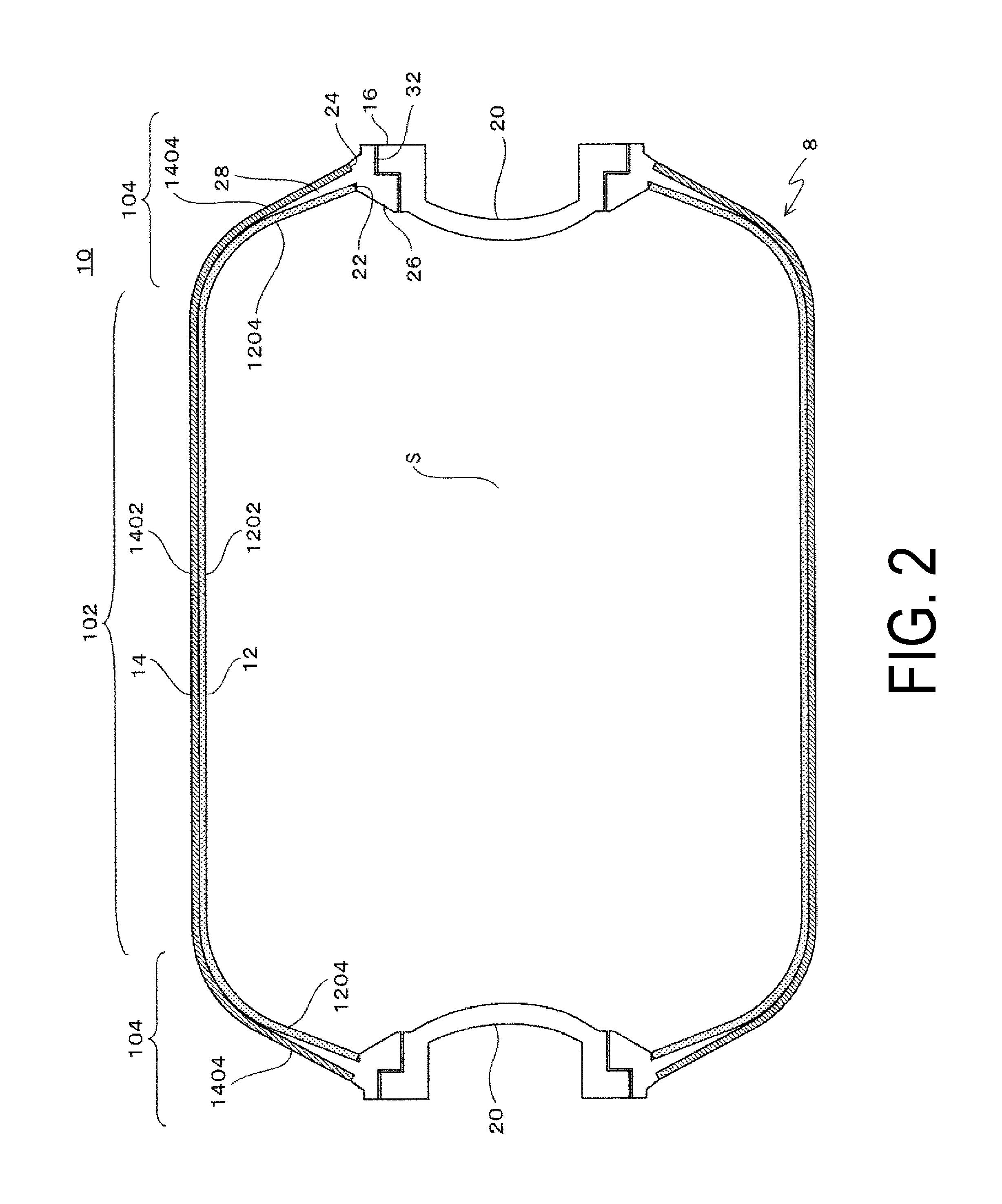
[0022]FIG. 1 is an external perspective view of an aircraft water tank according to an embodiment, FIG. 2 is a cross-sectional view along line A-A′ of the configuration of the aircraft water tank, and FIG. 3 is a cross-sectional view of the main parts of the aircraft water tank.

[0023]An aircraft water tank 8 is installed in an aircraft and serves to hold drinking water. As illustrated in FIG. 1, the aircraft water tank 8 is installed at a suitable location within the aircraft so that the lengthwise direction of the aircraft water tank 8 is horizontally disposed with two mouthpieces 16 being sealed by removable caps 20.

[0024]Water supply tank ports (water supply openings) 62 that communicate with the interior space S and are used to fill the tank with water or air or empty the tank of the same are provided at upward-facing locations at intermediate positions along the lengthwise directi...

second embodiment

[0054]Next, a second embodiment will be described with reference to FIGS. 4 and 5.

[0055]As illustrated in FIG. 4, the second embodiment differs from the first embodiment in that portions (opening-surrounding sections) 120 of the inner liner 12 surrounding the first openings 22 are thicker than the other parts thereof, and is otherwise similar to the first embodiment. In the embodiment described hereafter, elements identical or similar to those of the first embodiment are described using identical reference numerals.

[0056]The inner liner 12 of the second embodiment is formed from a polyolefin.

[0057]“Polyolefin” is a general term for polymers synthesized from an olefin or alkene monomer.

[0058]For example, polypropylene, a typical polyolefin, is a resin composed of polymerized propylene, and is one type of thermoplastic plastic. It has an ordinary heat resistance temperature of 100 to 140° C., and, at 0.9 to 0.91, the smallest specific gravity of all types of plastic. It is a material ...


PUM

PropertyMeasurementUnit
Circumferenceaaaaaaaaaa
Tensionaaaaaaaaaa

Abstract

An aircraft water tank constituting an aircraft water tank is provided with a cylindrical section, dome sections, and mouthpieces. The mouthpieces are provided with mouthpiece bodies and annular wall sections that extend outward in the radial direction around the entire outer circumferences of the mouthpiece bodies between an inner liner and a fiber-reinforced resin layer, and are attached to the inner liner and the fiber-reinforced resin layer around the circumferences of openings. Outer surfaces of the annular wall sections contacting the fiber-reinforced resin layer are formed by uniform tension curved surfaces.

Description

TECHNICAL FIELD[0001]The present technology relates to an aircraft water tank.BACKGROUND ART[0002]An aircraft water tank provided with a tank body comprising a cylindrical section and dome sections provided on both sides of the cylindrical section, and mouthpieces provided in the centers of the dome sections, has previously been proposed.[0003]The tank body is constituted by an inner liner in which is formed an interior space for holding water, and a fiber-reinforced resin layer covering an outer peripheral surface of the inner liner.[0004]Coaxial first and second openings in the inner liner and the fiber-reinforced resin layer are provided in the centers of the dome sections, and the mouthpieces are passed through the first and second openings and attached to the inner liner and the fiber-reinforced resin layer, and communicate with the interior space (see Japanese Unexamined Patent Application Publication No. 2011-251736A).[0005]FIG. 6 is a cross-sectional view illustrating the st...

Claims


Application Information

Patent Timeline
IPC IPC(8): B64D11/00B65D25/14B65D1/16B65D1/48
CPCB64D11/0007B65D1/16B65D25/14B65D1/48B64D11/02B29L2031/7154B29D22/003B29C70/086F17C2205/0305
Inventor MASUDA, MITSUTAKA
Owner YOKOHAMA RUBBER CO LTD
Why Eureka
Try Eureka