
Fluid sterilization system

a sterilization system and flue gas technology, applied in the field of sterilization, can solve the problems of limiting the disinfection power of uv light, static systems cannot be relocated to areas of increased infective potential, and high speed, and achieve the effect of convenient service and access

Active Publication Date: 2016-09-15
AEROBIOTIX
View PDF4 Cites 14 Cited by
  • Summary
  • Abstract
  • Description
  • Claims
  • Application Information

AI Technical Summary

Benefits of technology

The invention provides a way to catch and slow down organisms during a process of extreme heat. It also makes it easy to filter liquid and access the system for servicing.

Problems solved by technology

These systems have important disadvantages in that the fluid flows past the UV sources at a high rate of speed, limiting the disinfection power of the UV light.
Additionally, such static systems cannot be relocated to areas of increased infective potential.
Furthermore, mechanical filters, such as commonly employed HEPA systems, have limited effectiveness upon viruses and small bacteria.
Several portable fluid cleaner systems have been developed which utilize UV light, however such systems move fluid directly past ultraviolet sources, which limits concentration of the radiation and minimizes length of exposure.
Furthermore, such systems have no mechanism to capture organisms during the UV treatment process to maximize organism exposure.
Additionally, standard systems simply draw and release fluid in close proximity, which limits device effectiveness.

Method used


Image

  • Fluid sterilization system
  • Fluid sterilization system
  • Fluid sterilization system

Examples


Embodiment Construction

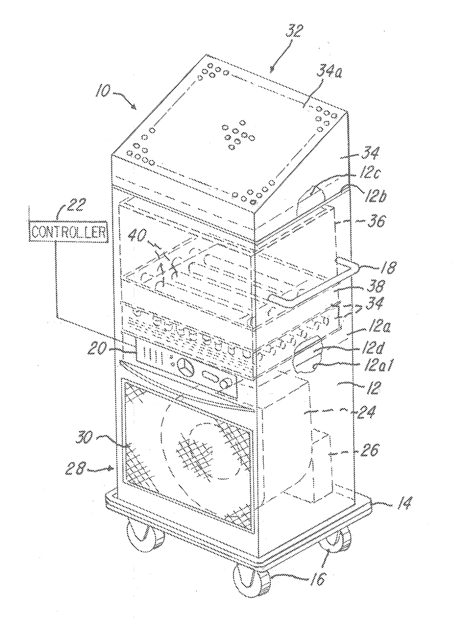
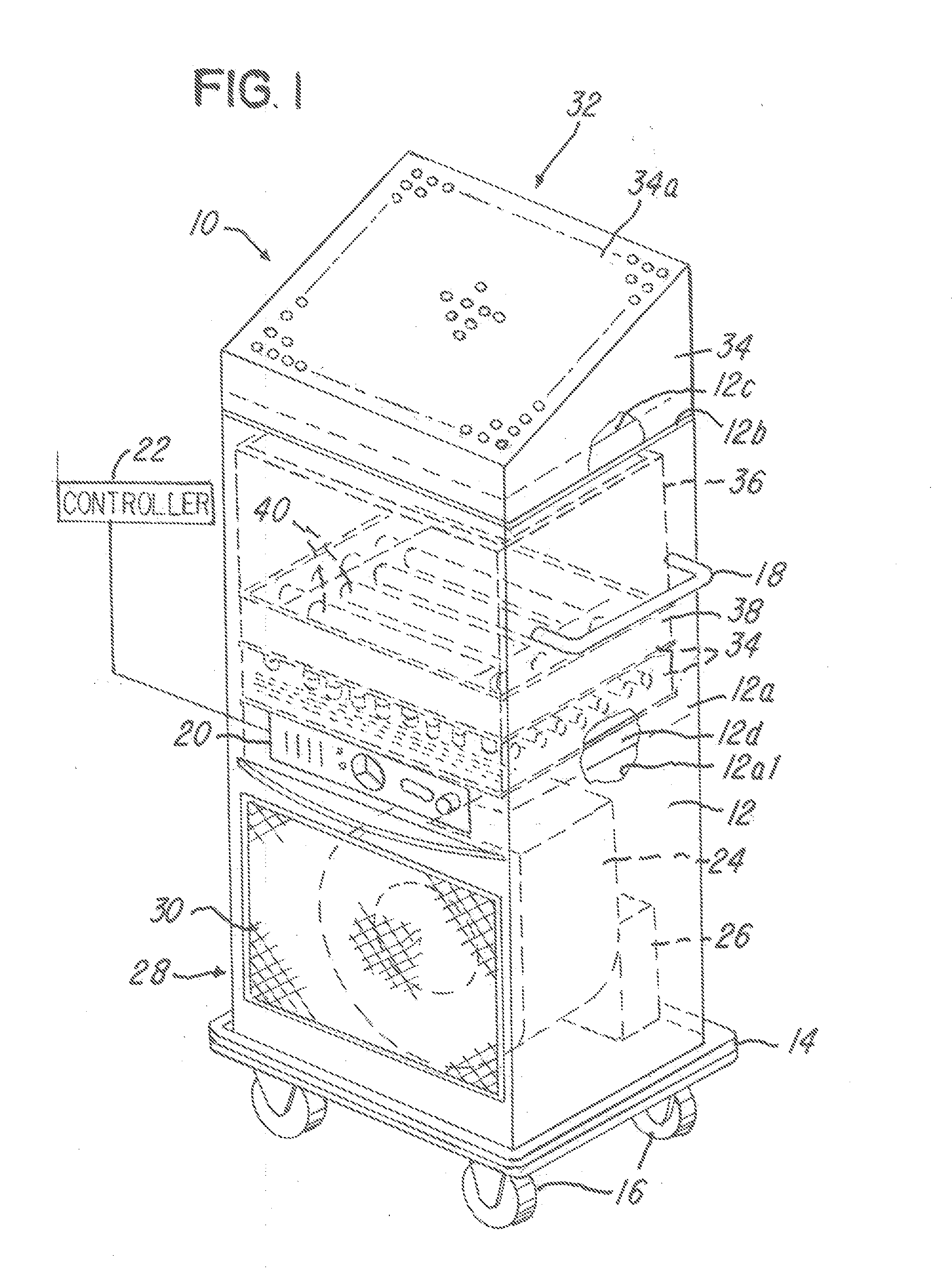
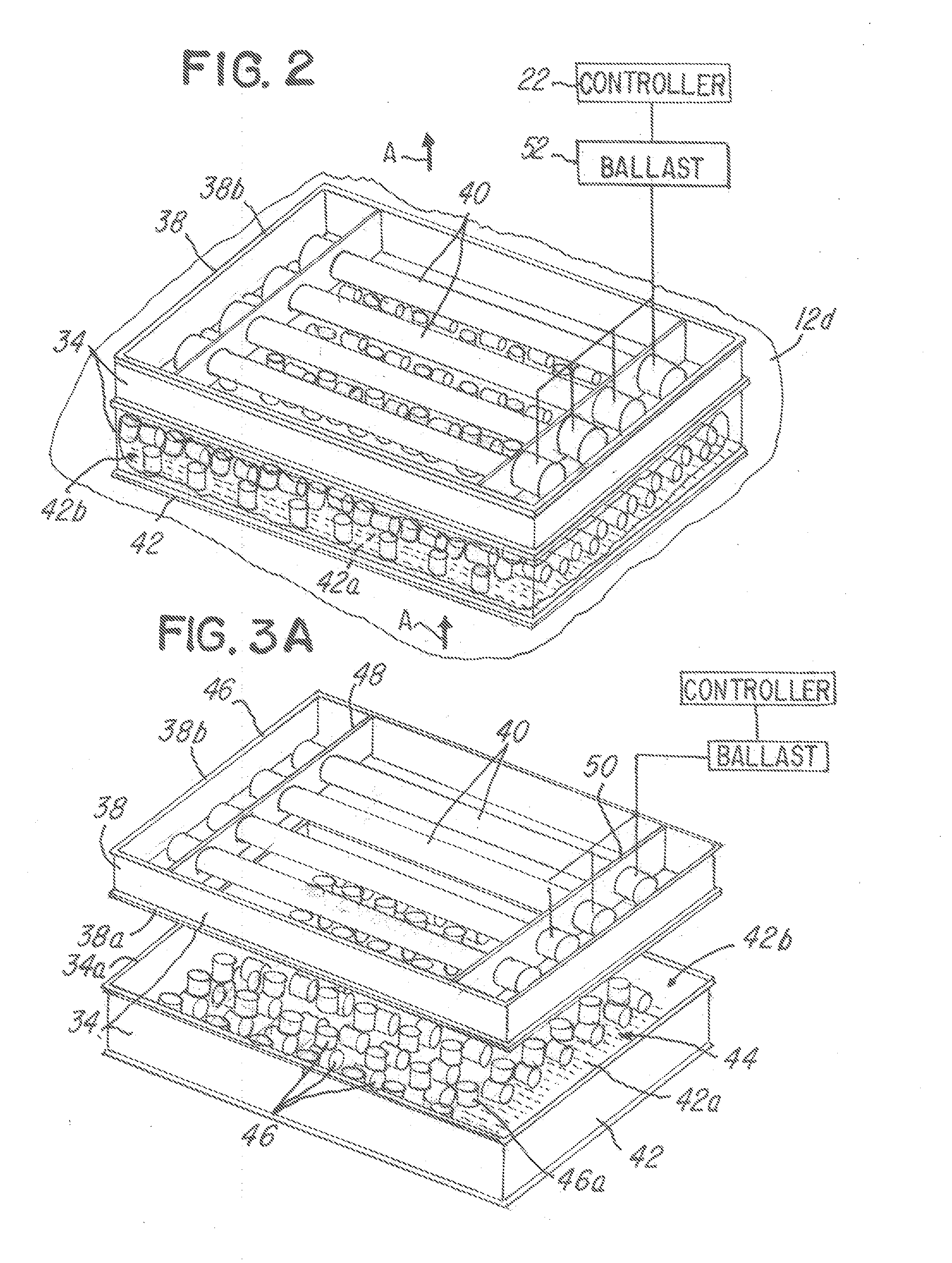
[0081]Referring now to FIGS. 1-13, embodiments of a fluid sterilization system 10 are shown. A first embodiment of the fluid sterilization system 10 is shown in FIGS. 1-5 and a second embodiment is shown in FIGS. 6-10. FIGS. 11-13 illustrate another embodiment of a fluid filtration assembly. For ease of illustration and description, like parts in each of the embodiments are identified with the like part numbers, except a prime mark (“′”) and a double prime mark (“″”) have been added to the second embodiments of FIGS. 6-10 and the third embodiment in FIGS. 11-13, respectively.

[0082]Referring now to FIGS. 1-5, the first embodiment of the fluid sterilization system 10 comprises a mobile housing unit 12 that is mobile and easily moved by hand. In the illustration being described, the mobile housing unit 12 is movable by hand using at least one or a plurality of handles 18 that are conventionally secured to a housing wall 12a of the mobile housing unit 12.

[0083]The mobile housing unit 12...


PUM

PropertyMeasurementUnit
shapesaaaaaaaaaa
shapeaaaaaaaaaa
circular shapeaaaaaaaaaa

Abstract

A fluid filtration system is shown. The fluid filtration system utilizes a one-piece or multiple piece containers having a plurality of radiation-transmissible media adapted to receive light, such as ultraviolet light, white light or other wavelength light. The radiation-transmissible media are situated in the container and at least one or a plurality of radiation sources, such as ultraviolet lamps, are situated in an array in proximity to the radiation-transmissible media. The radiation-transmissible media interrupts the flow and velocity of the fluid stream passing through the container to extend the duration of radiation for any contaminants and also provide enlarged surface areas for the contaminants to be received and ultimately exposed to the radiation. In one example, the radiation-transmissible media may be tubular or spherical sections that are hollow or solid and made of quartz.

Description

CROSS-REFERENCE TO RELATED APPLICATIONS[0001]The present application is a continuation of U.S. application Ser. No. 13 / 838,367, filed Mar. 15, 2013, which claims priority to provisional U.S. Application Ser. No. 61 / 735,623, filed Dec. 11, 2012, to which Applicant claims the benefit of the earlier filing date. These applications are incorporated herein by reference and made a part hereof.BACKGROUND OF THE INVENTION[0002]1. Field of the Invention[0003]This invention relates to sterilization and, more particularly, to a sterilization system that utilizes radiation-transmissible media to facilitate disinfecting a fluid stream.[0004]2. Background of the Invention[0005]There is a critical need to clean and sterilize room fluid in hospitals physician offices and operating room settings. Fluid borne bacteria and viruses cause disease and infection, particularly in health-care settings. Recently, there has been increased scrutiny placed upon the prevalence of hospital acquired infections, in...

Claims


Application Information

Patent Timeline
Patent Type & Authority Applications(United States)
IPC IPC(8): A61L9/20A61L2/26B01D46/00A61L2/08
CPCA61L9/20B01D46/0028A61L2/26A61L2/087B01D46/546B01D46/62B01D46/0002B01D2273/30A61L2209/14
Inventor KIRSCHMAN, DAVID LOUIS
Owner AEROBIOTIX
Learn More