Sensor arrangement and magnetization device, and use of the sensor arrangement in a motor vehicle control device

Active Publication Date: 2016-09-15
CONTINENTAL TEVES AG & CO OHG
View PDF11 Cites 20 Cited by
  • Summary
  • Abstract
  • Description
  • Claims
  • Application Information

AI Technical Summary

Benefits of technology

[0012]According to a particularly preferred embodiment of the sensor arrangement, the permanent magnet is magnetized as a magnetic dipole or as a magnetic quadrupole. In particular in the case of a magnetic quadrupole, magnetic stray fields can advantageously be significantly reduced, as a result of which in particular possible further adjacent functional assemblies, e.g. sensors, of the control device comprising the sensor arrangement are influenced to a lesser extent. Additional shielding of the magnetic field can furthermore be dispensed with, which is advantageous not just in the sense of the reduction of error sources of the sensor arrangement and the overall system, but also in the sense of reduced manufacturing costs and space requirement. The permanent magnet is preferably composed of a plastics-bonded neodymium iron boron (NdFeB) material.
[0013]With particular preference, the magnetic field sensor is spaced apart from the top surface of the permanent magnet such that said sensor is arranged within a region of a minimum of an angular error of the magnetic field of the permanent magnet. The distance between the magnet and the sensor can be advantageously reduced significantly as compared to the prior art, as a result of which in particular the space requirement is reduced. The location of the minimum of the magnetic angular error, for example with respect to the distance from the top surface of the magnet, is preferably adapted in an application-specific manner by a corresponding design of the sensor apparatus or by the features thereof and/or of the permanent magnet described in this application, wherein the magnet can also be located in the direct vicinity of the magnetic field sensor.
[0014]The permanent magnet is preferably fixed to a shaft, wherein the material of the permanent magnet is injection-molded around and/or to the shaft in particular in an injection-molding method. The manufacture and fixing of a base body, which is preferably magnetized in a subsequent process step to form the permanent magnet, are thus advantageously carried out in one process step. The result of this measure, in particular as compared to further mounting methods known per se, such as for example adhesively bonding the permanent magnet to the shaft, is not just the saving of manufacturing costs, but also the observation of necessary tolerances of modern motor

Problems solved by technology

Eddy currents, which can bring about further magnetic fields and thus likewise disturb the further f

Method used


Image

  • Sensor arrangement and magnetization device, and use of the sensor arrangement in a motor vehicle control device
  • Sensor arrangement and magnetization device, and use of the sensor arrangement in a motor vehicle control device
  • Sensor arrangement and magnetization device, and use of the sensor arrangement in a motor vehicle control device

Examples


Embodiment Construction

[0032]In order to permit a short and simple description of the exemplary embodiments, identical elements are provided with the same reference signs and only the details that are essential to the invention will be explained in each case.

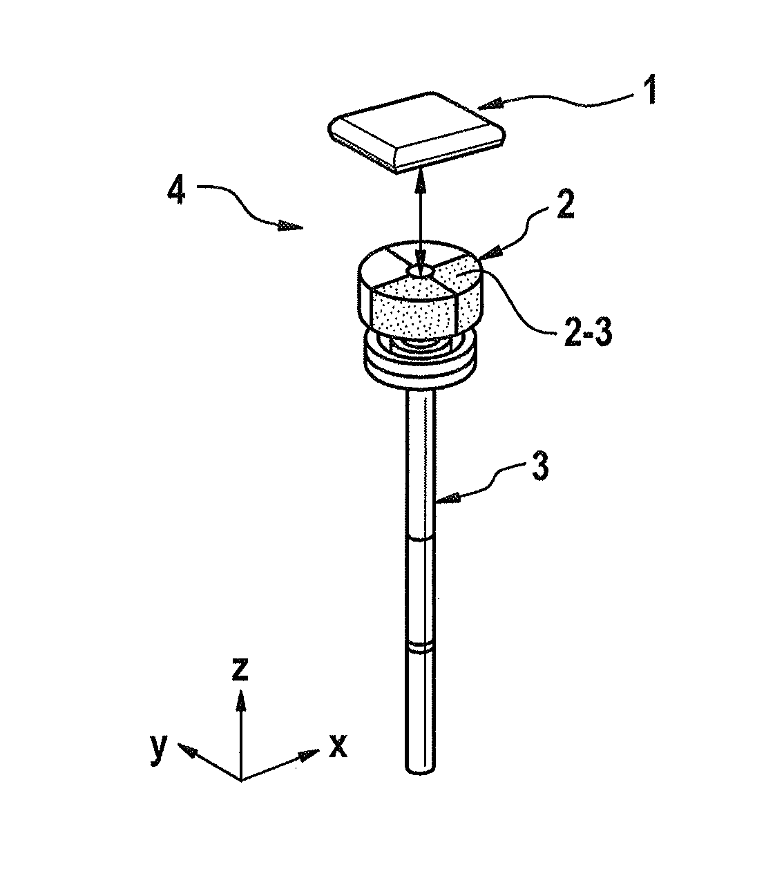
[0033]FIG. 1 shows a sensor arrangement 4, which is known per se, as is used in particular to support the commutation of an electric motor, for example of an electric motor of a linear actuator of a motor vehicle braking system and / or of a steering system of a motor vehicle, and is employed as an angle sensor arrangement or incremental transmitter. Said sensor arrangement 4 comprises at least sensor element 1 and the two-pole permanent magnet 2 that is fixed axially to the shaft 3 and the top surface 2-3 of which is orientated substantially perpendicularly to the z-axis and, according to this exemplary embodiment, parallel to the sensor element 1. The sensor element 1 is, according to an example, an AMR sensor which is arranged at an axial distance fr...


PUM


Abstract

A sensor arrangement for measuring a rotor position of an electric motor, in particular of a motor vehicle control device, wherein the sensor arrangement is constructed as a sensor arrangement operating without contact, which includes at least one permanent magnet and at least one magnetic field sensor, wherein the permanent magnet has at least one depression in at least one top surface facing the magnetic field sensor. A magnetization device for magnetizing a permanent magnet of the sensor arrangement is also disclosed. The use of the sensor arrangement in a motor vehicle control device of a braking system of a motor vehicle is also disclosed.

Description

CROSS REFERENCE TO RELATED APPLICATIONS[0001]This application is the U.S. National Phase Application of PCT International Application No. PCT / EP2014 / 070370, filed Sep. 24, 2014, which claims priority to German Patent Application No. 10 2013 224 135.6, filed Nov. 26, 2013 and German Patent Application No. 10 2014 200 365.2, filed Jan. 10, 2014, the contents of such applications being incorporated by reference herein.FIELD OF THE INVENTION[0002]The present invention relates to a sensor arrangement for a motor vehicle control device, to a magnetization apparatus for magnetizing a permanent magnet of the sensor arrangement, and to the use of the sensor arrangement in a motor vehicle control device.BACKGROUND OF THE INVENTION[0003]DE 10 2010 039 916 A1, which is incorporated by reference, describes a linear unit having a sensor device for capturing a rotor position of an electric motor, wherein the sensor device is configured as a contactlessly operating sensor arrangement which consists...

Claims


Application Information

Patent Timeline
IPC IPC(8): G01D5/16B60T8/171H01F7/06
CPCG01D5/16B60T8/171H01F7/064G01D5/145H01F13/003H02K11/215H01F13/00
Inventor BURGDORF, CHRISTIANPENZAR, ZLATKOSCHARDT, VOLKER
Owner CONTINENTAL TEVES AG & CO OHG
Why Eureka
Try Eureka