Beam steering ladar sensor

a beam steering and ladar sensor technology, applied in the field of laser sensors, can solve the problems of holographic capture systems, stereo systems, inability to demonstrate adequate performance in this application, etc., and achieve the effect of low cost and low parasitic packaging

Active Publication Date: 2016-09-15
CONTINENTAL AUTONOMOUS MOBILITY US LLC
View PDF2 Cites 76 Cited by
  • Summary
  • Abstract
  • Description
  • Claims
  • Application Information

AI Technical Summary

Benefits of technology

[0009]In other embodiments, each ladar sensor may have a focal plane array of detectors of indium gallium arsenide formed on a substrate of indium phosphide, gallium arsenide, or silicon. In a further embodiment, an electrical amplifier array may be interposed between the focal plane array of optical detectors and the readout integrated circuit. In yet another embodiment, the electrical amplifier array and the readout integrated circuit may be provided with through hole vias through the substrate to eliminate wirebonds, and thereby enable the low cost and low parasitic packaging of the focal plane array and readout integrated circuit.

Problems solved by technology

Stereo systems, holographic capture systems, and those which acquire shape from motion, have not been able to demonstrate adequate performance in this application, but 3D LADAR based systems have shown the ability to rapidly capture 3-D images of objects and roadway features in the path of a moving vehicle, or travelling on an intersecting path, with sufficient speed and accuracy to allow the host vehicle to avoid collisions and road hazards, and steer the best path.

Method used


Image

  • Beam steering ladar sensor
  • Beam steering ladar sensor
  • Beam steering ladar sensor

Examples


first embodiment

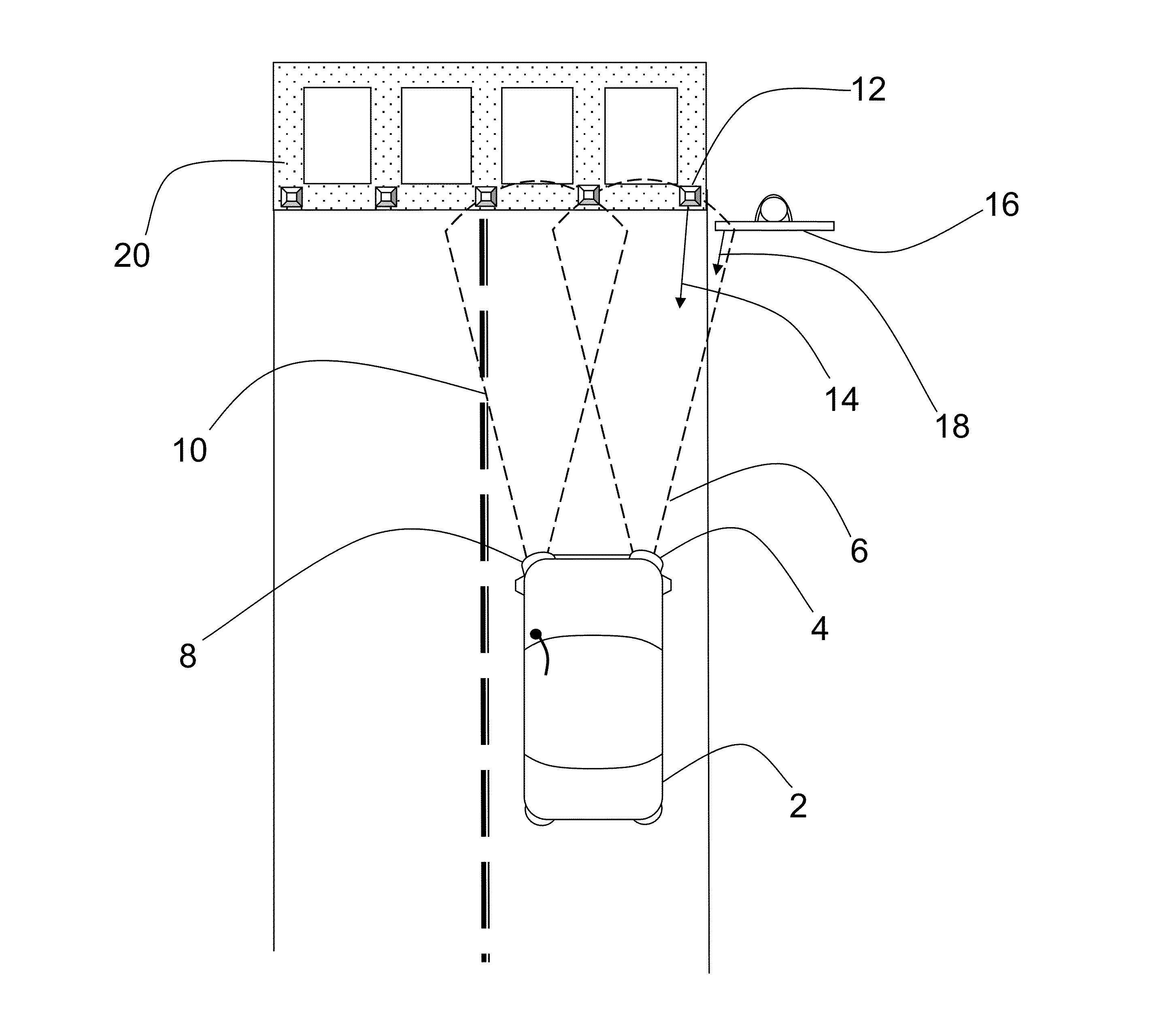
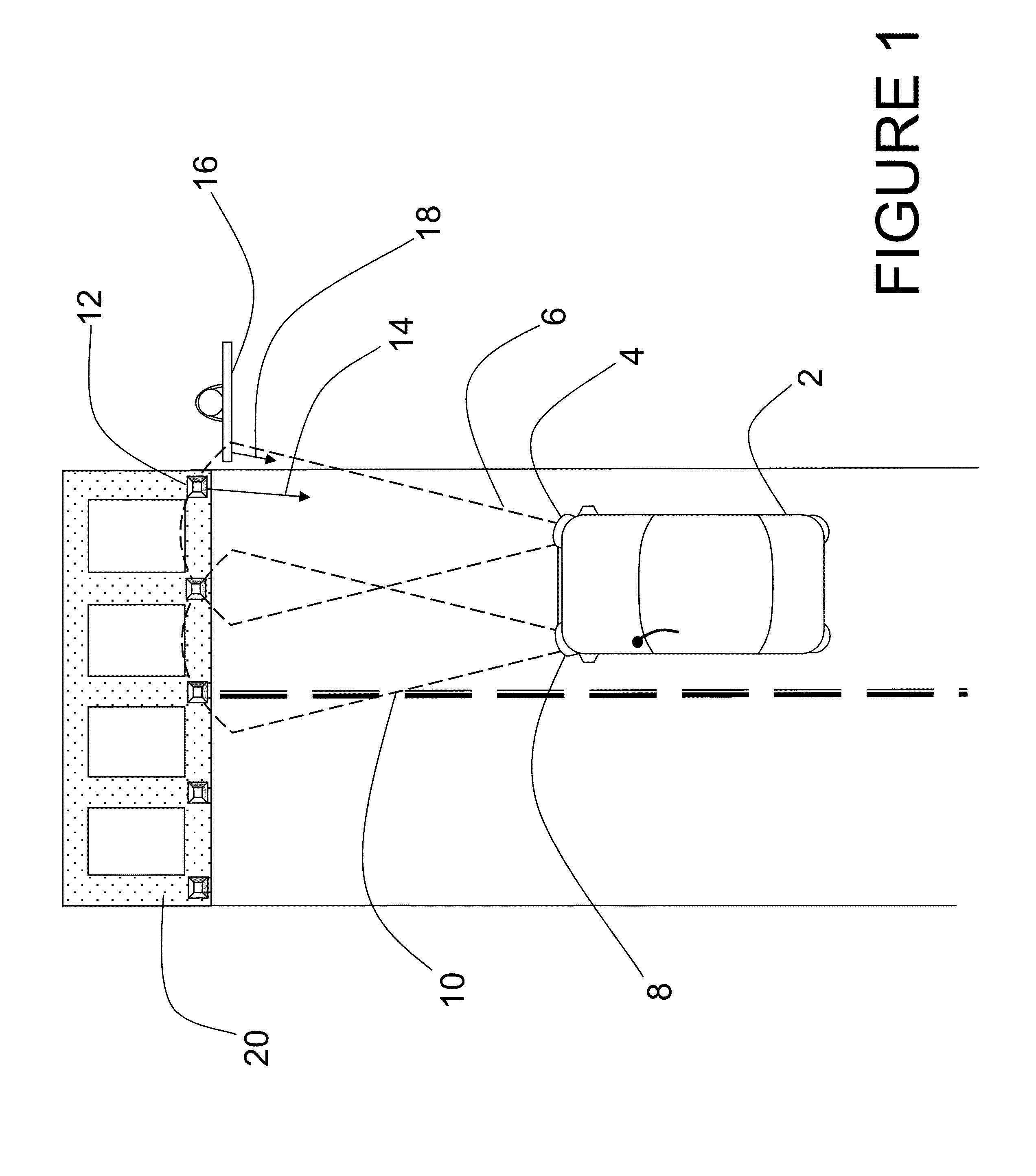
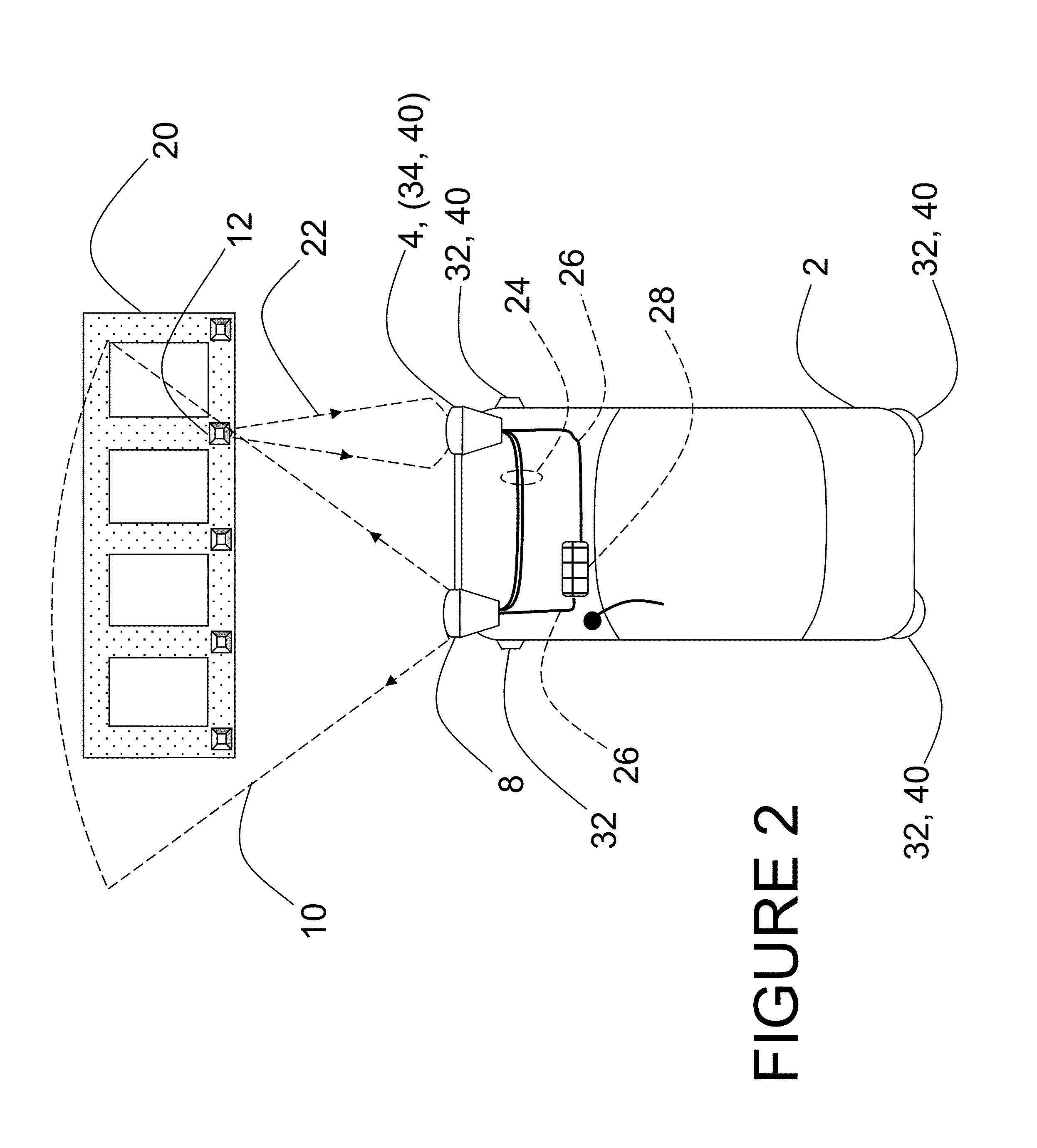
[0046]FIG. 4 is a block diagram of a ladar sensor which describes both long range ladar sensors 34 and short range sensors 32 typical of the preferred embodiment. Major improvements described herein include the addition of a beam steering mechanism 70, an optical gain block 76, an electronic amplifier array 80, and new detector and focal plane array (FPA) packaging options. The first embodiment provides a 128×128 or 128×64 detector array 78 of light detecting elements which is stacked atop a readout integrated circuit 82 using a hybrid assembly method. In other embodiments of the design, M×N focal plane arrays of light detecting elements with M and N having values from 2 to 1024 and greater are anticipated. The functional elements depicted in FIG. 4 may first be described with respect to the elements of a typical long range ladar sensor 34. A control processor 58 controls the functions of the major components of the ladar sensor 34. Control processor 58 connects to pulsed laser tran...

second embodiment

[0056]FIG. 6B shows a central section view of beam steering mechanism 70. Several embodiments of the beam steering mechanism 70 are anticipated, and each is described in association with a FIGS. 6A, 6B, 6C, and 6D. The operating mode of the beam steering mechanism 70 will be then described in connection with the operations of the ladar sensor (32, 34). A silicon substrate 150 is processed via photolithography and MEMs fabrication techniques to have a cavity 156, cantilevered bending element 158, and two recessed sections for mounting an edge emitting laser 152, and a beam conditioning lens 154 on a first surface. Beam conditioning lens 154 is typically a ball lens or a rod lens, but may be of another type useful for circularizing and / or collimating the elliptical output beam of edge emitting laser 152. The output beam of edge emitting laser 152 is directed by lens 154 to fall on the mirror surface 160 of bending element 158. Mirror surface 160 may be gold, silver, aluminum, nickel, ...

third embodiment

[0057]FIG. 6C shows a central section view of beam steering mechanism 70. A first silicon substrate 168 is processed via photolithography and MEMs fabrication techniques to have a cavity 178, and a first cantilevered bending element 180, and two recessed sections for mounting an edge emitting laser 170, and a beam conditioning lens 172 on the top surface. A third recessed section 175 is formed by MEMs techniques, such as chemical mechanical polishing. Recessed section 175 has an angled profile on the sidewalls, and a mirrored surface 174. Beam conditioning lens 172 is offset vertically from the centerline of the output beam of laser 170, and redirects the beam onto mirrored surface 174. Beam conditioning lens 172 is typically a ball lens or a rod lens, but may be of another type useful for circularizing and / or collimating the elliptical output beam of edge emitting laser 170. The optical beam is then directed against the mirror surface 190 of a second bending element 188. Second ben...


PUM


Abstract

A beam steering capability is proposed for a ladar sensor operating with limited laser transmit power, as may be typical of an airborne or automotive application. The ladar system also makes use of optical gain elements in the receiver which act to increase the signal to noise ratio at the receiver when the laser transmit power available is restricted by power, size, and/or cost limitations. In one embodiment, the calibration of each pixel in the ladar sensor is provided for by an electrical amplifier array with a number of pixel amplifiers. Each pixel amplifier may be individually calibrated to a mating detector element so as to eliminate the variations in dark current and gain between all pixels in the detector array. A number of new detector array designs are described which may lower cost and improve performance, and new low cost and high performance packaging for the detector array, amplifier array, and readout integrated circuit is introduced.

Description

BACKGROUND[0001]1. Field of the Invention[0002]The embodiments disclosed herein relate generally to 3-D image generation and the identification and tracking of objects, and more particularly to LADAR sensors for mobile applications such as road hazard avoidance, collision avoidance, and autonomous navigation. The invention compensates for the issues arising from the operation of a ladar sensor having a limited optical power output.[0003]2. References to Related Art[0004]The 3-D imaging technology disclosed in Stettner et al, U.S. Pat. Nos. 5,446,529, 6,133,989 and 6,414,746 provides with a single pulse of light, typically pulsed laser light, all the information of a conventional 2-D picture along with the third dimensional coordinates; it furnishes the 3-D coordinates of everything in its field of view. This use is typically referred to as flash 3-D imaging in analogy with ordinary digital 2-D cameras using flash attachments for a self contained source of light. As with ordinary 2-D...

Claims


Application Information

Patent Timeline
Patent Type & Authority Applications(United States)
IPC IPC(8): G01S7/481G01S17/93G01S7/4863G01S17/894G01S17/931
CPCG01S7/4814G01S7/4811G01S7/4817G01S17/936G01S7/4863G01S2013/93277G01S17/931G01S17/894
Inventor GILLILAND, PATRICKSTETTNER, ROGER
Owner CONTINENTAL AUTONOMOUS MOBILITY US LLC
Why Eureka
Try Eureka