Motor driving apparatus including life determining unit of direct-current capacitor

a technology of direct-current capacitor and motor driving apparatus, which is applied in the direction of capacitor testing, power supply testing, instruments, etc., can solve the problems of capacitor failure, increase the fluctuation of direct-current voltage, so as to accurately determine the life

Active Publication Date: 2016-09-22
FANUC LTD
View PDF0 Cites 11 Cited by
  • Summary
  • Abstract
  • Description
  • Claims
  • Application Information

AI Technical Summary

Benefits of technology

[0012]In light of the above-described problems, an objective of the present invention is to provide a motor driving apparatus that can accurately determine the life of each of a plurality of direct-current capacitors corrected in parallel in a direct-current link between a converter and inverters.

Problems solved by technology

When the capacity of the direct-current capacitor decreases, the ripple current running through the direct-current link increases, to increase the fluctuation in direct-current voltage increases, which is problematic.
When the capacity of the direct-current capacitor provided in the direct-current link between the converter and the inverter in the motor driving apparatus decreases by repetition of charge and discharge as described above, the ripple current running through the direct-current link increases, to increase the fluctuation in direct-current voltage, which is problematic.
Unless the capacity of the direct-current capacitor can be measured accurately, the timing of exchanging the direct-current capacitor may be missed, which has a possibility of causing a large ripple current in the direct-current link or a fluctuation in direct-current voltage, or of exchanging a direct-current capacitor still alive too early.
In other words, a direct-current capacitor having ended its life cannot be identified from a plurality of direct-current capacitors, which is not convenient.

Method used


Image

  • Motor driving apparatus including life determining unit of direct-current capacitor
  • Motor driving apparatus including life determining unit of direct-current capacitor
  • Motor driving apparatus including life determining unit of direct-current capacitor

Examples


Embodiment Construction

[0026]The motor driving apparatus including a life determining unit of a direct-current capacitor will be described below with reference to the drawings. However, it is noted that the present invention is not limited by the drawings and the embodiment described below.

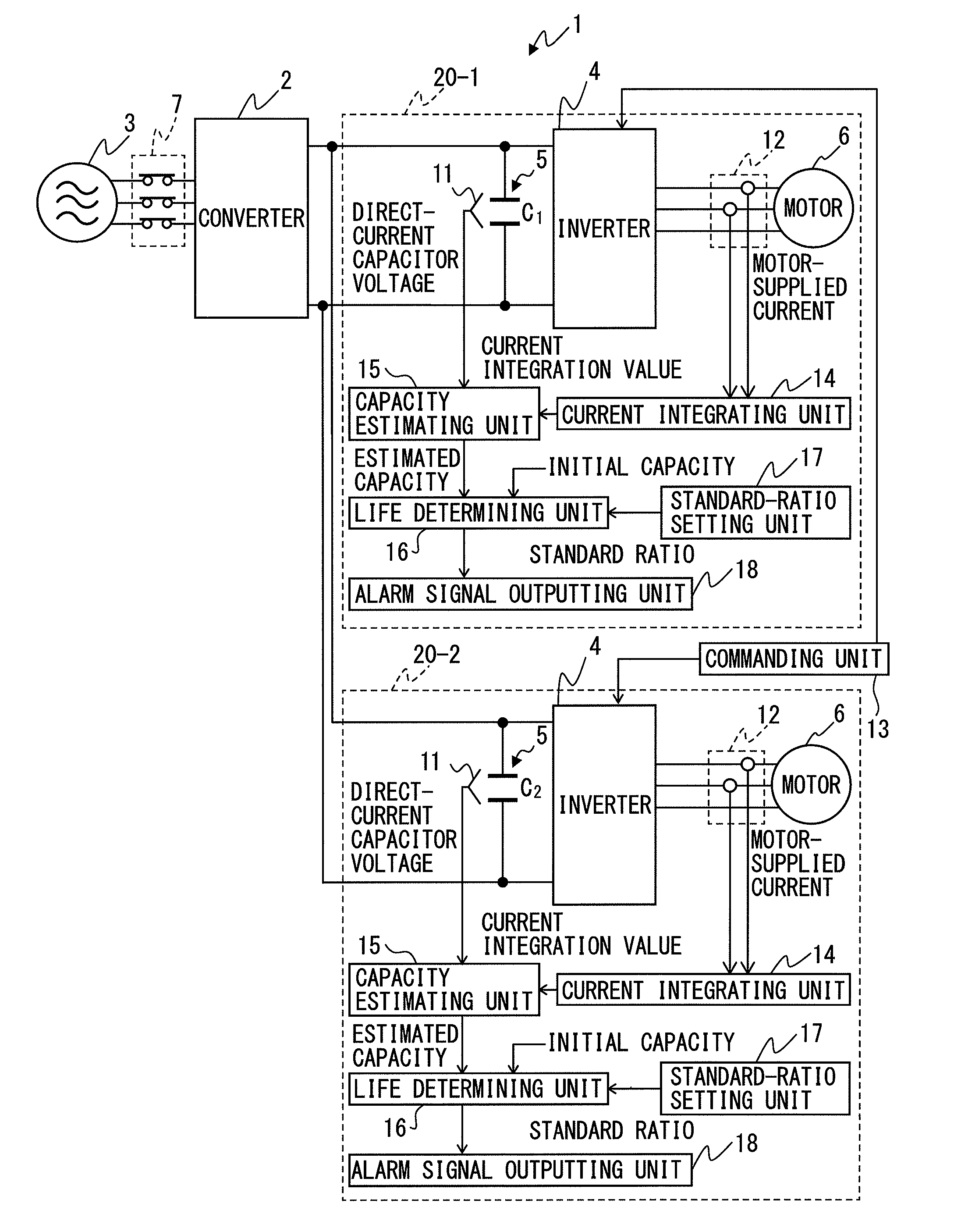
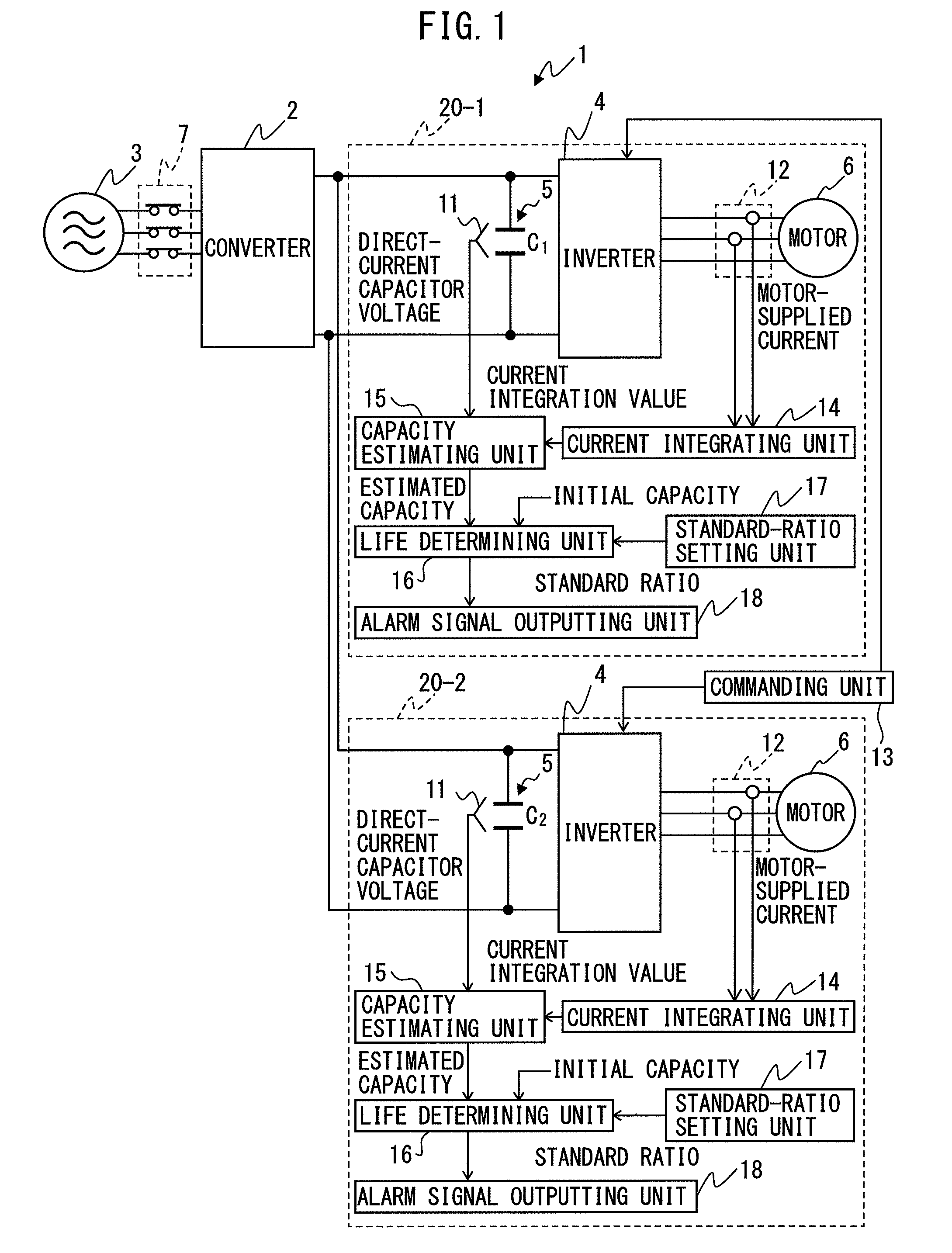
[0027]The number of direct-current capacitors to be provided in a motor driving apparatus according to the present invention is at least two in the direct-current link. In the exemplary embodiment explained below, a case in which two motors are driven by a motor driving apparatus is explained as one example. The type of motors driven by the motor driving apparatus are not particularly limit the present invention, and may be an induction motor or a synchronous motor, for example.

[0028]First, a circuitry configuration of a motor driving apparatus according to the first embodiment example is explained. FIG. 1 is a principle block diagram depicting a motor driving apparatus according to a first embodiment example. Hereafter...


PUM


Abstract

A motor driving apparatus includes: a voltage detecting unit for detecting a voltage of each direct-current capacitor; a current detecting unit for detecting each current inputted to or outputted from each inverter; an commanding unit for outputting a power-converting command to each inverter after each direct-current capacitor is charged and supply of direct-current power to a converter is shut off; a current integrating unit for integrating each current detected while the power-converting command is outputted; a capacity estimating unit for calculating the estimated capacity of each direct-current capacitor based on the current integration value and the voltage of the direct-current capacitor after supply of direct-current power to the converter is shut off and before the power-converting command is outputted; and a life determining unit for determining a life of each direct-current capacitor based on the initial capacity value and the estimated capacity of the direct-current capacitor.

Description

BACKGROUND OF THE INVENTION[0001]1. Field of the Invention[0002]The present invention relates to a motor driving apparatus that converts an alternating-current power supplied from the three-phase alternating current input into a direct-current power and outputs the same to the direct-current link, and thereafter further converts the same into an alternating-current power for driving the motor and supplies the same to the motor. In particular, the present invention relates to a motor driving apparatus including a life determining unit for determining the life of a direct-current capacitor provided in the direct-current link.[0003]2. Description of the Related Art[0004]In a motor driving apparatus for driving a motor in machine tools, industrial machines, forging machines, injection molding machines, or various types of robots, an alternating-current power inputted from the alternating-current power source is first converted into a direct-current power by means of a converter, and the...

Claims


Application Information

Patent Timeline
Patent Type & Authority Applications(United States)
IPC IPC(8): G01R31/02H02P27/06H02P6/10H02M1/00H02M1/32H02M7/5387
CPCG01R31/028H02P27/06H02P6/10G01R27/2605H02P5/74H02M1/32H02M5/458H02M7/5387G01R31/42G01R31/64H02M1/008
Inventor YOSHIDA, TOMOKAZU
Owner FANUC LTD
Why Eureka
Try Eureka