Microstructured materials

a microstructured material and material technology, applied in the field of materials, can solve the problems of low mechanical and functional properties, low yield, and low yield of filaments with a majority of high flow-temperature polymers, and achieve the effects of reducing surface roughness, preserving dimensional stability, and high mechanical and functional properties

Active Publication Date: 2016-09-29
US SEC THE ARMY THE
View PDF0 Cites 35 Cited by
  • Summary
  • Abstract
  • Description
  • Claims
  • Application Information

AI Technical Summary

Benefits of technology

[0013]According to one object of the invention, provided are preforms or filaments that are formed of one or more materials such as but not limited to a thermoplastic, glass, metal, edible material, or other material. In some aspects, a filament or preform contains two or more polymers of differing flow temperature. The two or more materials are optionally in a regular geometric arrangement within the filament or preform cross-section. This arrangement results in a structure optionally with a processing temperature window in which the lower flow temperature (LFT) polymer flows in order to fill voids and form strong weld lines, while the higher flow temperature (HFT) polymer remains mechanically stable to retain dimensional stability. By printing or annealing FFF parts within this processing window, parts with high mechanical and functional properties, as well as reduced surface roughness that also maintain geometric accuracy can be produced.

Problems solved by technology

This blended material typically exhibits flow and sag characteristics equivalent to an average of the properties of the individual polymer phases, and does not provide any distinct advantages over conventional FFF monofilament feedstock.
For blended filaments with a majority of low flow-temperature polymer, heating the filament leads to bulk softening of the filament, since the random and likely disconnected arrangement of the higher flow-temperature polymer does not provide a means of efficiently supporting mechanical load.
Similarly, blended filaments with a majority of high flow-temperature polymer are unlikely to exhibit good flow and bonding at lower temperatures, as much of the low flow-temperature polymer is likely to be trapped within the higher flow-temperature polymer.
In addition to compromises in mechanical and geometric characteristics, insufficient weldline fusing also compromises functional properties of conventional FFF parts.
Heating the part can be used to flow the polymer, eliminating the voids and creating a transparent part, but geometric accuracy will be lost.
As-printed weldlines are unlikely to have electrical conductivity as high as the original feedstock, because the conductive filler cannot fully disperse and make contact across the weld line.
Heating the part can reduce or eliminate the weldlines, potentially increasing filler-to-filler contact and therefore electrical conductivity, but geometric accuracy will be lost.
However, such extrusion dies are complex and expensive to design and fabricate, and require long lead times and specialized skill to create and implement.
Combining multiple materials, in particular, via co-extrusion requires multiple extruders and very complex die arrangements that can dramatically increase manufacturing costs.
It is rarely economical to co-extrude more than three different polymers, placing a further limitation on this approach.

Method used


Image

  • Microstructured materials
  • Microstructured materials
  • Microstructured materials

Examples


example 1

[0095]A preform is made using an acrylonitrile butadiene styrene (ABS) LFT polymer core with a glass transition temperature (Tg) of approximately 105° C., and extruded acrylic (PMMA) HFT polymer sheath with a Tg of approximately 125° C. The source materials for the core were obtained from Stratasys (Eden Prairie, Minn.). The source materials for the extruded acrylic sheath is from McMaster Carr (Robbinsville, N.J.). The preform combines a printed ABS core made on a dual-head MAKERBOT REPLICATOR 2× (MAKERBOT Industries, LLC, Brooklyn, N.Y.) inserted within an extruded acrylic tube. The core was sized with some interference so that the fit into the sheath was mechanically tight. The resulting preform is illustrated in FIG. 2A. Thermally drawing this material resulted in monofilament such as shown in FIG. 2B, with an outer diameter of 2.5 mm while accurately replicating the original geometry of the preform. This example shows that dual materials can be co-drawn with this process, and t...

example 2

[0096]A preform is made using a printed polycarbonate (PC) core and an extruded polycarbonate tube. The source materials for the core were obtained from Stratasys (Eden Prairie, Minn.), while the extruded polycarbonate tubing is from McMaster Carr (Robbinsville, N.J.). The preform combines a printed PC core made on a Stratasys Fortus (Eden Prarier, Minn.) where the core includes a relatively complex cross shape that is maintained when inserted within an extruded PC tube. The resulting preform is illustrated in FIGS. 3A and B.

[0097]The preform is thermally drawn down to monofilament to create a four-lobed microfluidic fiber with opaque inner walls and an optically transparent outer wall such as shown in FIGS. 3C and 3D, with an outer diameter of approximately 600 μm while accurately replicating the original geometry of the preform. This example shows that dual materials can be co-drawn with this process while maintaining the shape of the original preform and relative dimensions there...

example 3

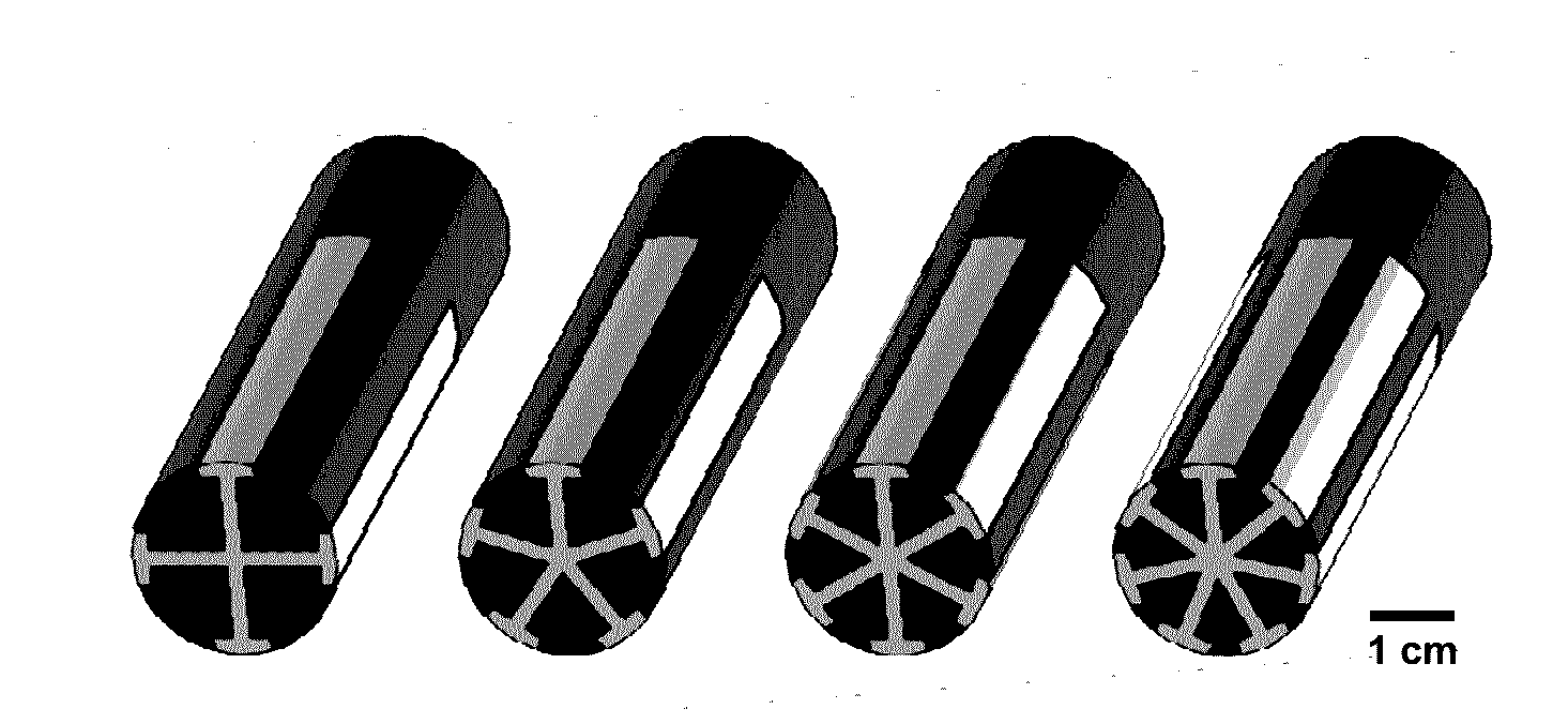
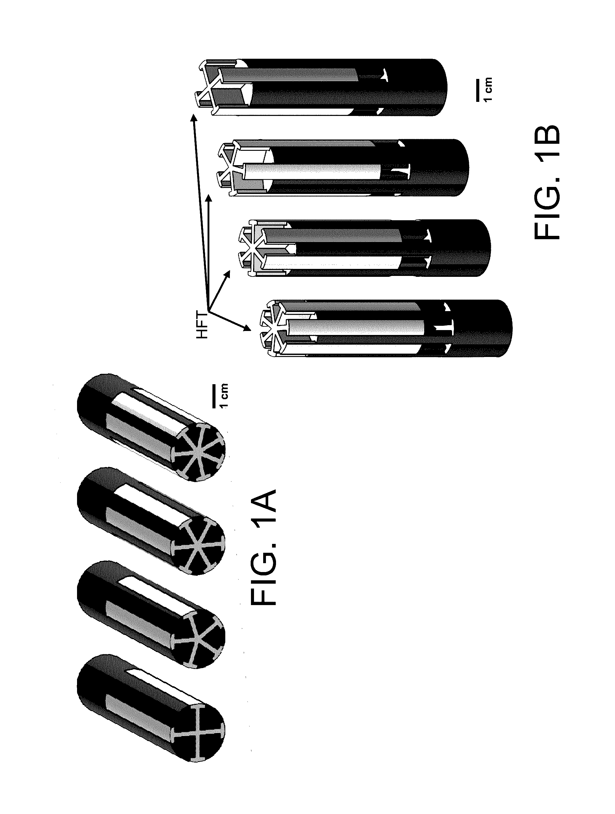
[0099]Complex interlocking preforms are produced by independently printing by FFF processes two independent interlocking shapes, the LFT polymer is ABS with a glass transition temperature (Tg) of approximately 105° C., and the HFT polymer is polycarbonate (PC) with a Tg of approximately 147° C. The individual polymer shapes are printed using a Stratasys Fortus (Eden Prarier, Minn.). The two components were sized with some interference so that the fit when combined was mechanically tight. The two components are fit together to produce the preform as illustrated in FIG. 5A illustrating the two elements in an intermediately combined state.

[0100]The preform is thermally drawn down to a five-lobed monofilament with interlocking polymers as shown in FIG. 5B, with an outer diameter of approximately 1.6 mm while accurately replicating the original geometry of the preform. The preform is thermally drawn to a finer scale, five-lobed filament with interlocking polymers as shown in FIG. 5C, wit...


PUM

PropertyMeasurementUnit
diameteraaaaaaaaaa
diameteraaaaaaaaaa
outer diameteraaaaaaaaaa

Abstract

A thermoplastic filament comprising multiple polymers of differing flow temperatures in a regular geometric arrangement, and a method for producing such a filament, are described. Because of the difference in flow temperatures, there exists a temperature range at which one polymer is mechanically stable while the other is flowable. This property is extremely useful for creating thermoplastic monofilament feedstock for three-dimensionally printed parts, wherein the mechanically stable polymer enables geometric stability while the flowable polymer can fill gaps and provide strong bonding and homogenization between deposited material lines and layers. These multimaterial filaments can be produced via thermal drawing from a thermoplastic preform, which itself can be three-dimensionally printed. Furthermore, the preform can be printed with precisely controlled and complex geometries, enabling the creation of monofilament and fiber with unique decorative or functional properties.

Description

CROSS-REFERENCE TO RELATED APPLICATIONS[0001]This application claims priority to and the benefit of U.S. Provisional Application No. 62 / 139,313, titled “Geometrically Regular, Multi-Material Polymer Filament for Three-Dimensional Printing” filed on Mar. 27, 2015 which is hereby incorporated by reference herein including all attachments and papers filed with U.S. Provisional Application No. 62 / 139,313.GOVERNMENT INTEREST[0002]The invention described herein may be manufactured, used, and licensed by or for the United States Government.FIELD[0003]The present invention relates generally to the field of materials. More specifically, materials and devices are provided for use in production of complex fibers for many applications such as three-dimensional printing methods and systems, optical fibers, electronic fibers, or microfluidic fibers, among other applications. In particular aspects, materials and material structures are provided that provide superior capabilities in formation of co...

Claims


Application Information

Patent Timeline
Patent Type & Authority Applications(United States)
IPC IPC(8): D01F8/10D01F8/18C03B37/023D01F8/14
CPCD01F8/10D01F8/14D01F8/18D10B2331/04D10B2321/08D10B2321/10C03B37/023C03B37/027C03B37/028C03B2201/06C03B2201/32C03B2201/70C03B2201/86D01D5/30D01F8/00B33Y70/00C03B19/00G02B6/02314B29C64/118B29C64/106G02B6/00B29C66/5241G02B6/02033B29D11/00701B29C66/53D10B2401/20B29C65/565B29D11/00663B29L2031/731B29C66/5221B29C66/61B29L2011/0075B29D11/00721B33Y40/20Y10T428/2929Y10T428/2975B33Y80/00
Inventor WETZEL, ERIC D.HOLMES, JR., LARRY R.RODRIGUEZ, RICARDO X.TOAL, JR., PATRICK M.
Owner US SEC THE ARMY THE
Why Eureka
Try Eureka