Nested-Flow Heat Exchangers and Chemical Reactors

a heat exchanger and chemical reactor technology, applied in the field of nested-flow heat exchangers and chemical reactors, can solve the problems of limiting the efficiency of the total heat exchanger, high cost and long delivery time of the heat exchanger, and the complexity of the circuit heat exchanger, so as to improve the energy efficiency of the process, reduce the cost, and improve the effect of cos

Active Publication Date: 2016-09-29
BAYOTECH INC
View PDF2 Cites 16 Cited by
  • Summary
  • Abstract
  • Description
  • Claims
  • Application Information

AI Technical Summary

Benefits of technology

[0023]It is a primary objective of the present invention to provide a heat exchanger which is more cost effective per unit of energy transferred at the same driving temperature than we have today.
[0024]It is another objective of the present invention to provide a chemical reactor that incorporates heat transfer between the reactant and the products at a sufficiently low cost that the reactor will provide a significantly improved energy effic

Problems solved by technology

But the construction technique for making printed circuit heat exchanger is quite complex and only a limited production capability exists, resulting in both high cost and long delivery times for these heat exchangers.
A higher cost heat exchanger technology limits the total heat exchanger efficiency due to the tradeoff between heat exchanger cost and replacement energy cost.
In addition to the low energy efficiency of today's SMR process, the capital cost of the system is high due to the strength of material required for the SMR reaction tubes.
These tubes are operated at high temperatures, while coupled to a low pressure source of heat; forcing their construction from expensive materials, adding significantly to the cost of the SMR system.
The process is slightly exothermic, and in today's system

Method used


Image

  • Nested-Flow Heat Exchangers and Chemical Reactors
  • Nested-Flow Heat Exchangers and Chemical Reactors
  • Nested-Flow Heat Exchangers and Chemical Reactors

Examples


Embodiment Construction

1. Definitions

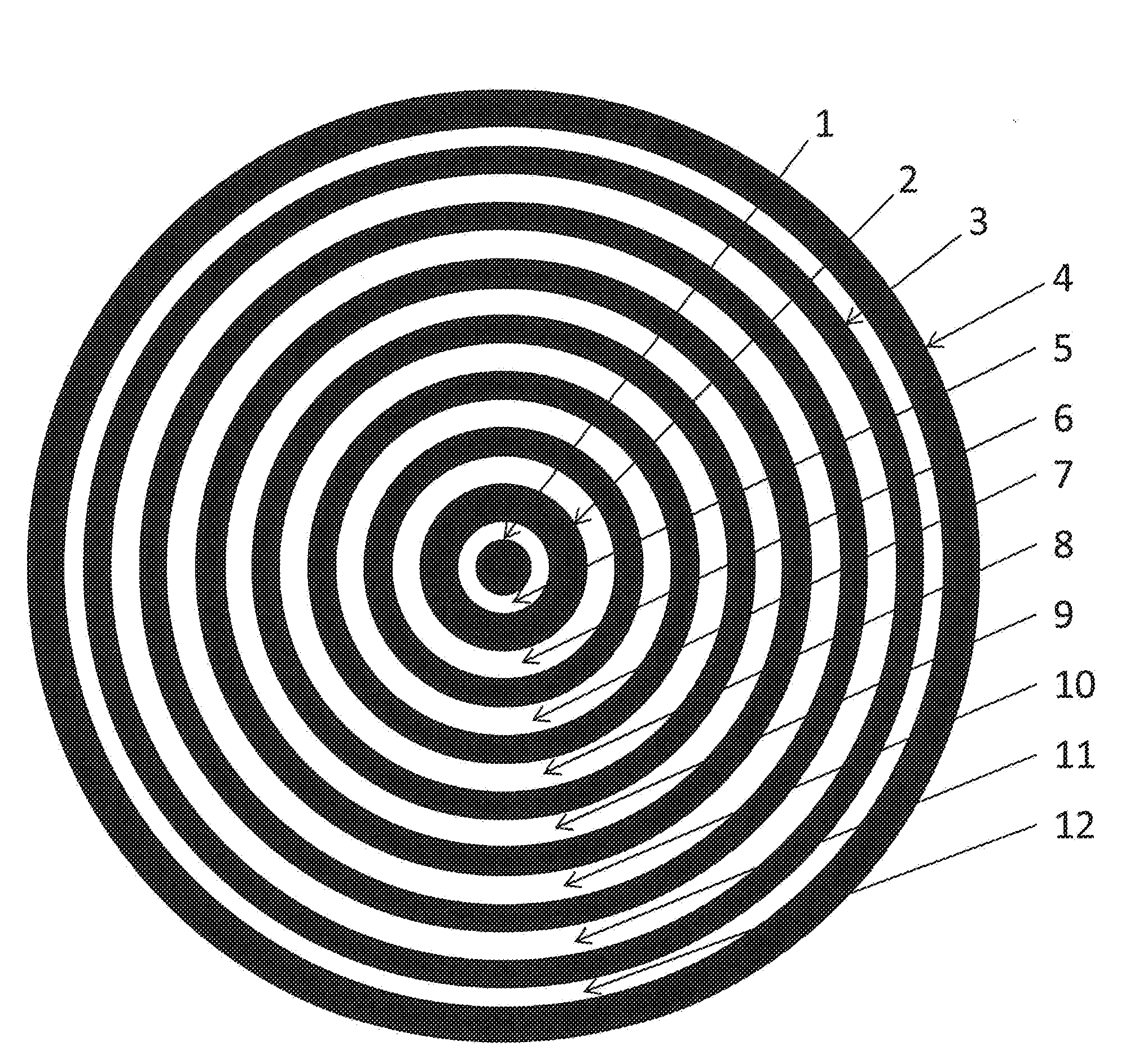
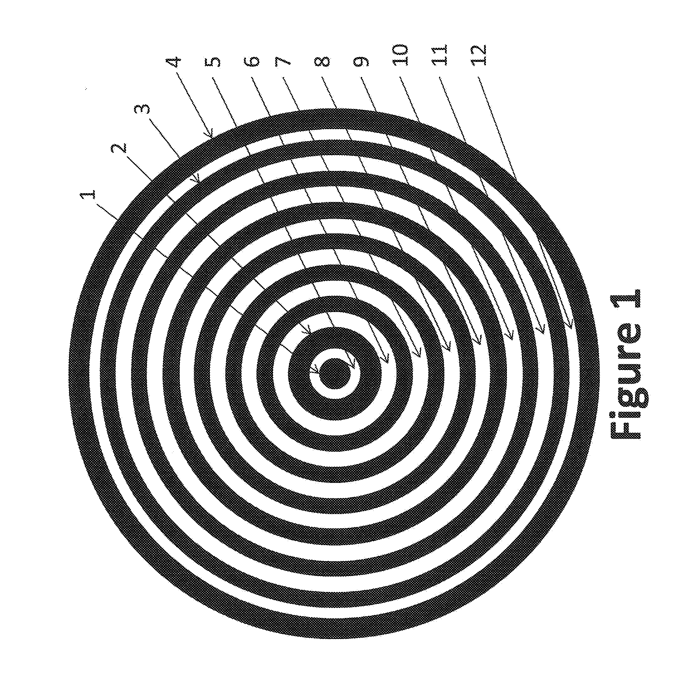
[0035]Nested-flow technology as used herein shall mean a system of nested tubes with associated flow channels, created by those tubes, which are maintained as open flow channels through the use of spacers within those flow channels.

[0036]Single nested-flow unit as used herein shall mean a group of nested tubes with a common axial centerline, more or less, providing as many flow channels as desired.

[0037]Manifold nested-flow unit as used herein shall mean more than one single nested-flow unit assembled onto a common manifold for achieving desired product flow rates.

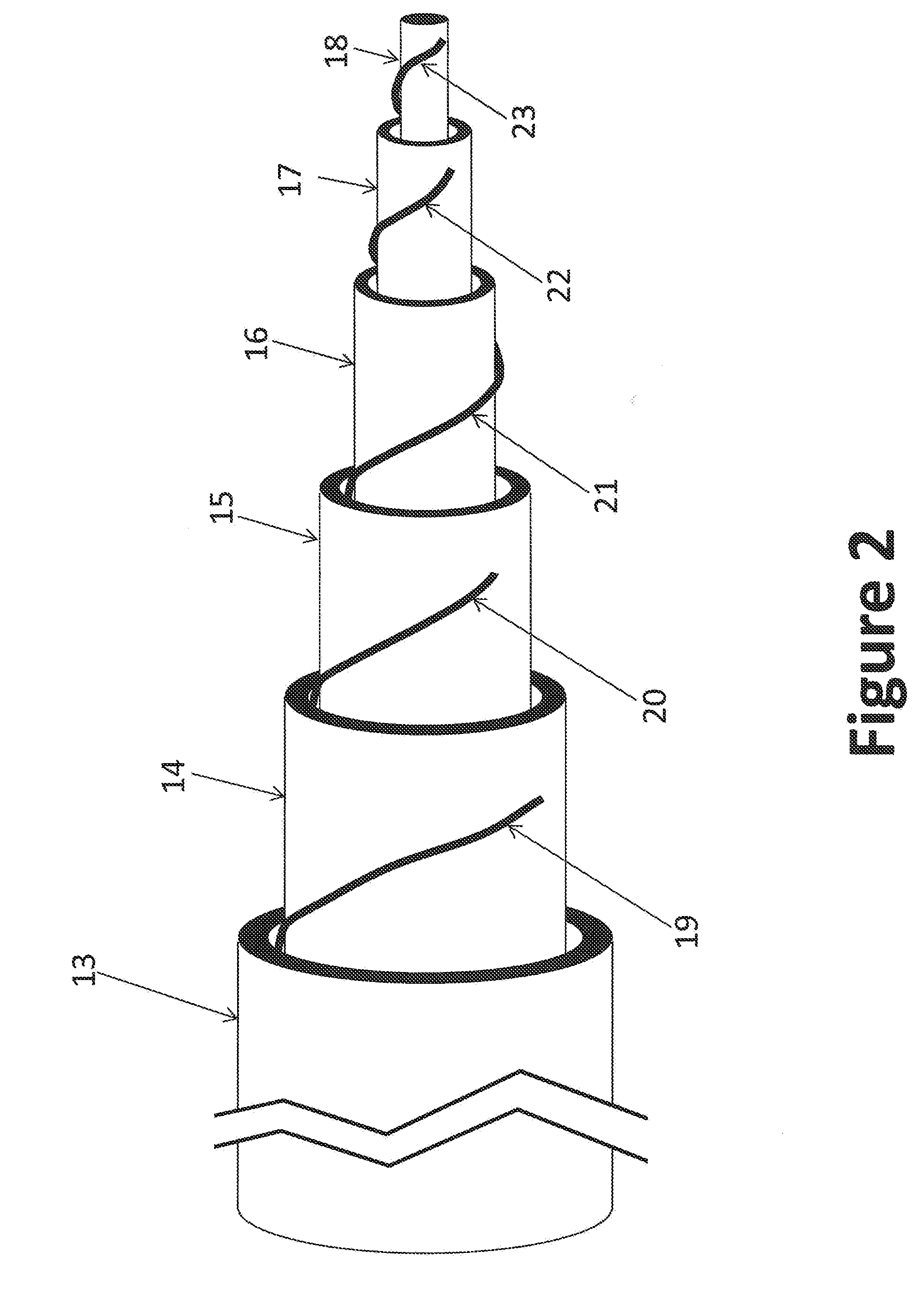
[0038]Wire wrap as used herein shall mean the installation of a small rod or wire spiraling from one end of a tube to the other end. The wire wrap can spiral fairly quickly from one end of the tube to the other, meaning that several inches of tube length would be incorporated for each wrap around the tube. The wire in this wire wrap need not be metal, but shall be compatible to the tube onto which it is wrapp...


PUM


Abstract

Disclosed is a technology based upon the simple nesting of tubes to provide heat exchangers, chemical reactors or chemical reactors with built in heat exchanger. As a chemical reactor, the technology provides the ability to manage the temperature within a process flow to better control the process for improved performance, control the location of product production to control corrosion issue, or implement multiple steps for a process within the same piece of equipment. As a heat exchanger, the technology can provide large surface areas per unit volume and large heat transfer coefficients. As a combined heat exchanger and chemical reactor, the technology can recover the thermal energy from the product flow to heat the reactant flow to the reactant temperature, significantly reducing the energy needs for accomplishment of a process. Combined heat exchanger and chemical reactor examples for hydrogen production and ammonia production are presented, along with a urea production example that integrates the product formation, resonance time conversion and stripping steps for urea production all within a single process unit.

Description

STATEMENT REGARDING FEDERALLY SPONSORED R&D[0001]This invention was made without Government support.BACKGROUND OF THE INVENTION[0002]1. Field of the Invention[0003]The present invention relates to equipment for processing chemicals and other fluid cycles bases on temperature change, including power cycles. The equipment includes heat exchangers and chemical reactors. The present invention significantly reduces the capital investment required for this type of equipment through use of standard construction techniques and materials. The present invention also significant improved heat transfer performance, where needed, which significantly reduces energy consumption for product production.[0004]2. Description of the Prior Art[0005]Heat exchangers and chemical reactors are commonly used equipment in chemical processing and recuperated power cycles. This equipment is used in a broad spectrum of industries and in all stages of processing.[0006]Heat exchangers are used to transfer heat (th...

Claims


Application Information

Patent Timeline
IPC IPC(8): F28D7/10C01C1/04B01J7/00B01J15/00B01J19/00C07C273/04C05C9/00F28F9/013F28F13/08F28F13/06F28F13/12F28F9/02H01M8/04082H01M8/04007C01B3/48
CPCF28D7/103H01M2250/10C01C1/0482C01C1/0488C01C1/0417B01J7/00B01J15/005B01J19/0046B01J19/0013C07C273/04C05C9/00F28F9/0137F28F13/08F28F13/06F28F13/12F28F9/0221H01M8/04201H01M8/04067C01B2203/0233C01B2203/0283C01B2203/068C01B2203/0811C01B2203/142B01J2219/00495B01J2219/00745B01J2219/0072B01J2219/00117C01B3/48B01J8/008B01J8/0257B01J8/0278B01J8/0285B01J8/0465B01J12/007B01J2208/00212B01J2208/00309B01J2208/0053B01J2208/025C01B3/384C01B2203/1241C01B2203/82F28D7/12F28D2021/0022F28F1/122H01M8/0618Y02B90/10Y02E60/50Y02P20/10Y02P20/141Y02P20/52
Inventor VERNON, MILTON EDWARD
Owner BAYOTECH INC
Why Eureka
Try Eureka