Spectrometry device and image forming apparatus

Active Publication Date: 2016-09-29
SEIKO EPSON CORP
View PDF7 Cites 32 Cited by
  • Summary
  • Abstract
  • Description
  • Claims
  • Application Information

AI Technical Summary

Benefits of technology

[0007]An advantage of some aspects of the invention is to provide a spectrometry device a

Problems solved by technology

As such, if the distance signal is calculated on the basis of the light reception signal, correction accuracy (color measurement accuracy) decreases because measurement noise affects the light reception signal, and a problem arises in that a spectrometry process (colorimetry process) cannot be performed with sufficient accuracy.
Thus, the cost and the size of the spectrometry device are decreased.
In this case, the intens

Method used


Image

  • Spectrometry device and image forming apparatus
  • Spectrometry device and image forming apparatus
  • Spectrometry device and image forming apparatus

Examples


first embodiment

[0033]Hereinafter, a first embodiment according to the invention will be described on the basis of the drawings. In the present embodiment, hereinafter, a printer 10 (ink jet printer) that includes a spectrometry device will be described as an example of an image forming apparatus of the invention.

Schematic Configuration of Printer

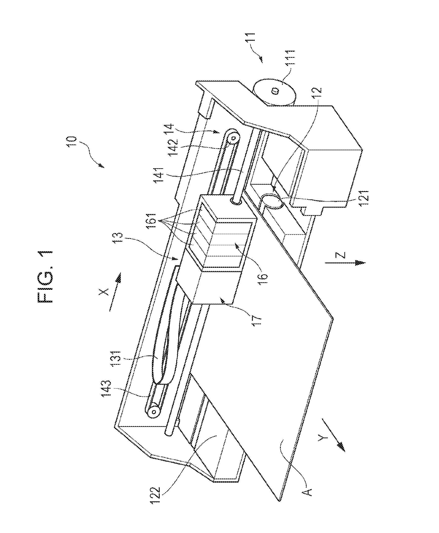
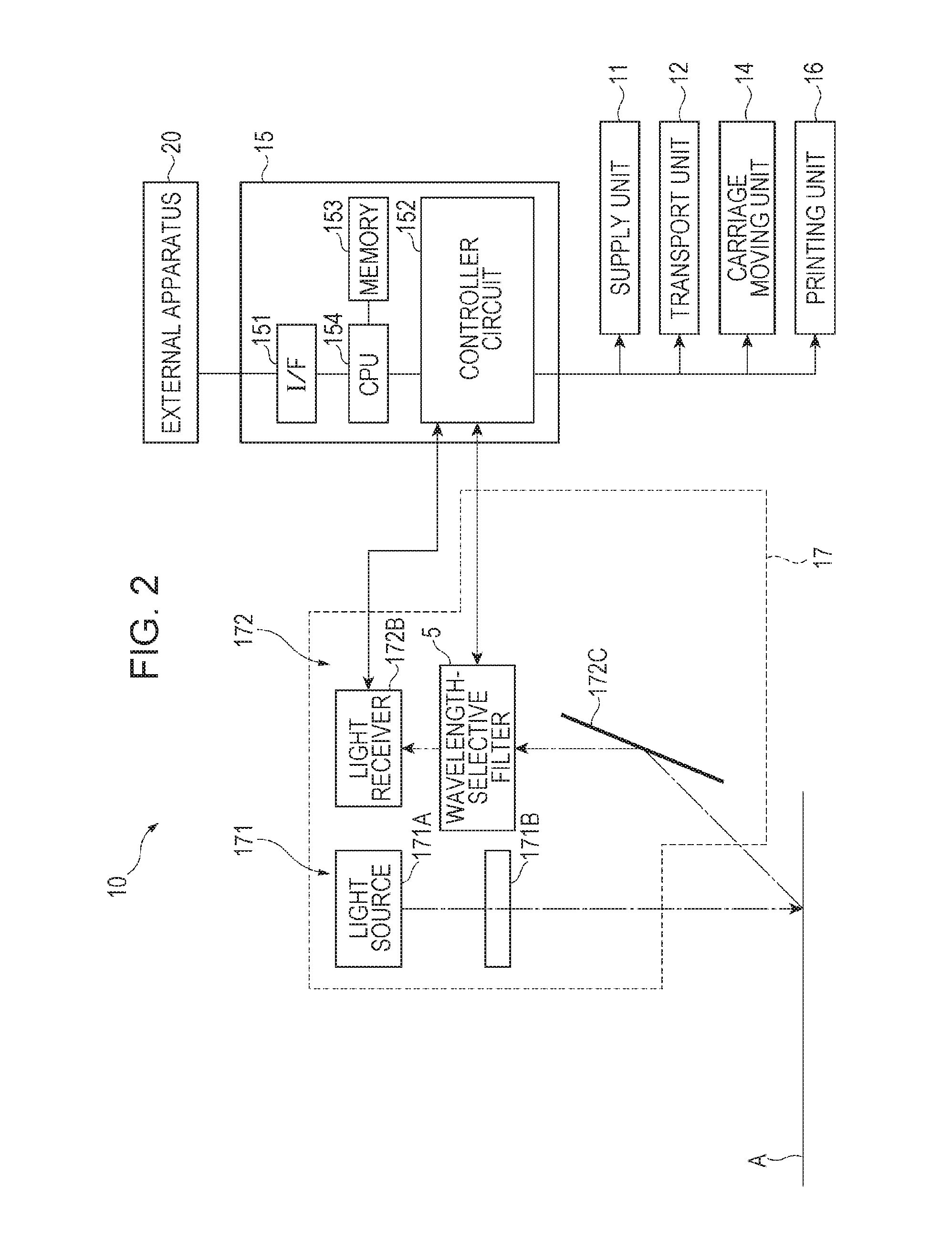
[0034]FIG. 1 is a diagram illustrating an exterior configuration example of the printer 10 of the present embodiment. FIG. 2 is a block diagram illustrating a schematic configuration of the printer 10 of the present embodiment.

[0035]As illustrated in FIG. 1, the printer 10 includes a supply unit 11, a transport unit 12, a carriage 13, a carriage moving unit 14, and a control unit 15 (refer to FIG. 2). The printer 10 controls each of the units 11, 12, and 14 and the carriage 13 on the basis of print data that is input from an external apparatus 20 such as a personal computer and prints an image on a medium A (which constitutes a measurement target and an im...

second embodiment

[0110]Next, a second embodiment according to the invention will be described.

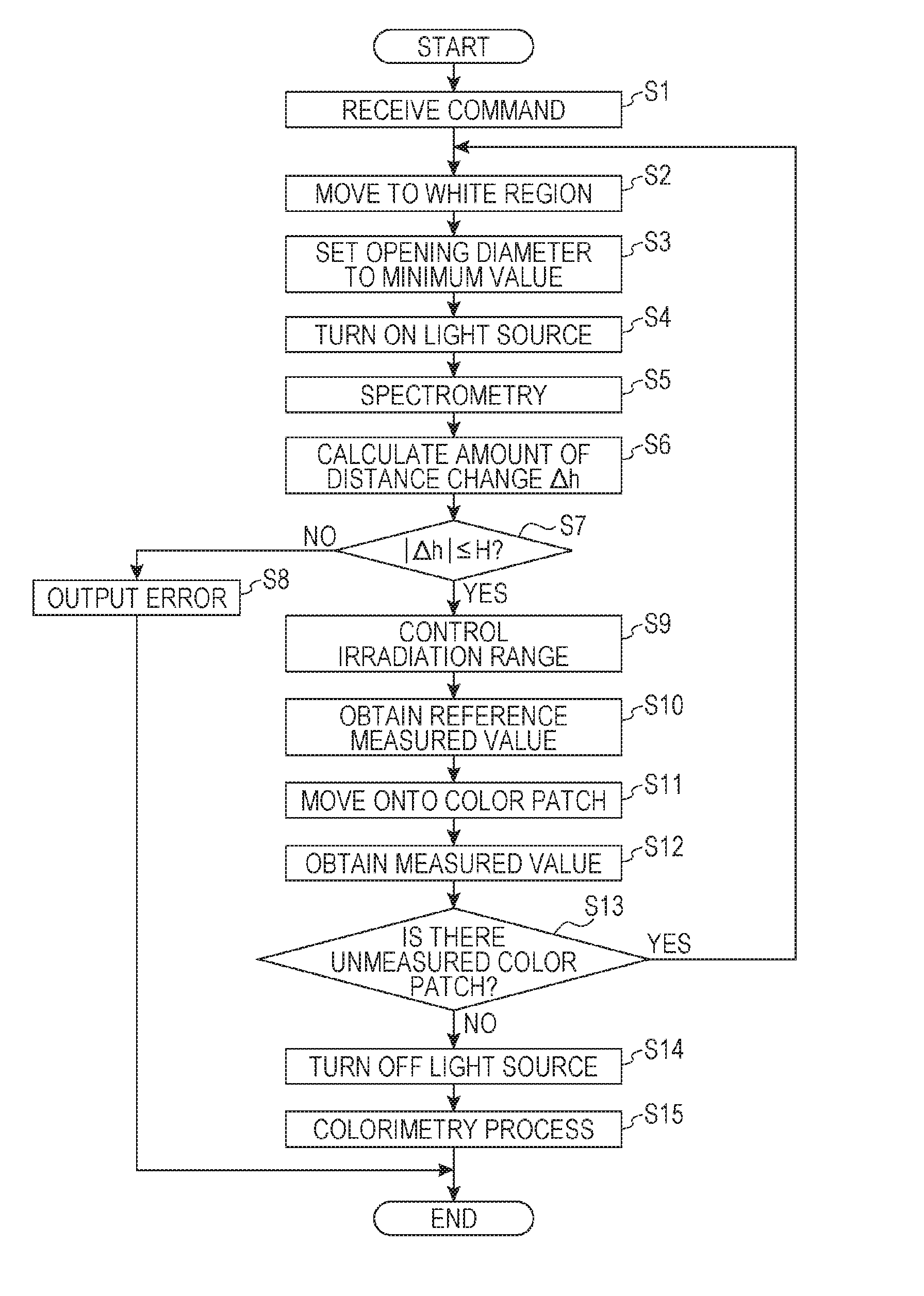
[0111]In the first embodiment, the integrator optical system 171B irradiates the predetermined area of irradiation B with the illumination light from the light source 171A and ensures approximate uniformity of the in-plane intensity distribution of the illumination light. In this case, while the area of measurement R can be irradiated with illumination light having an approximately uniform intensity distribution, a region other than the area of measurement R is also irradiated with the illumination light. Thus, measurement error may be caused by stray light.

[0112]Regarding this matter, the second embodiment is different from the first embodiment in that measurement error due to stray light is reduced by disposing a light pencil diameter changer that can change an opening diameter thereof.

[0113]FIG. 7 is a diagram illustrating a schematic configuration of a spectroscope 17A of the present embodiment. In the ...


PUM


Abstract

A printer includes a spectroscope including a light source, an integrator optical system that irradiates a predetermined area of irradiation of a medium with illumination light from the light source, a spectroscopy device on which light from a measurement target is incident and in which a wavelength-selective interference filter is disposed, and a light receiver that receives light emitted from the spectroscopy device. The integrator optical system irradiates with the illumination light the area of irradiation that includes a reference area of measurement and is larger than the reference area of measurement by at least an allowable amount of change in the distance between the medium and the spectroscope or more, the reference area of measurement in which the distance between the medium and the spectroscope is equal to a reference distance.

Description

BACKGROUND[0001]1. Technical Field[0002]The present invention relates to a spectrometry device and to an image forming apparatus.[0003]2. Related Art[0004]In the related art, there is known, in an image forming apparatus such as a color printer, a device that measures the color of a color image (color patch or the like) formed by the image forming apparatus and provides feedback of a color measurement result to the image forming apparatus in order to form the color image desired by a user with high accuracy (for example, refer to JP-A-2010-210456).[0005]The device disclosed in JP-A-2010-210456 irradiates the medium with light by using a light source in which the central portion is bright while the peripheral portion is dark and receives reflected light by using a light receiver that is divided into a plurality of light receiving regions. Then, a distance signal corresponding to the distance between the medium and the colorimeter is calculated on the basis of a light reception signal...

Claims


Application Information

Patent Timeline
IPC IPC(8): G01J3/26B41J29/393G01J3/02
CPCG01J3/26B41J29/393G01J3/0208B41J2/00G01J3/00G02B5/28B41J29/38G01J3/021G01J3/10G01J3/50H04N1/00002
Inventor KANAI, MASASHI
Owner SEIKO EPSON CORP
Why Eureka
Try Eureka