Welding method for shell and tube

a shell and tube heat exchanger technology, applied in indirect heat exchangers, manufacturing tools, light and heating equipment, etc., can solve the problems of lowering welding efficiency, difficult welding operation, and lowering productivity

Active Publication Date: 2016-10-06
SEWON CELLONTECH CO LTD
View PDF5 Cites 2 Cited by
  • Summary
  • Abstract
  • Description
  • Claims
  • Application Information

AI Technical Summary

Benefits of technology

[0021]In a shell and tube welding method in accordance with the present invention, under the condition that a tube joint member and a tube having the same diameter are inserted into each of tube insertion holes formed through tube sheets of a shell and tube heat exchanger and contact each other, a welding torch is inserted into the tube joint member to perform welding and, thus, the welding torch may easily approach targets for welding, and part

Problems solved by technology

That is, in order to directly weld the outer sides of the tubes 10 to the shell side of the tube sheet 20 using the welding torch T, welding of tubes 10 located at the edge region of the tube sheet 20 is possible but, when other adjacent tubes 10 or other tubes 10 located at the central region of the tube sheet 20 are welded to the tube sheet 20, interference between the tube 10 and the tube 10 occurs and thus welding is difficult, welding efficiency is lowered and complete welding operation is difficult.
However, since welding heat of the welding touch T is not directly transmitted to the tube sheet lower end joint part 23 of the tube sheet 20 welded to the outer circumferen

Method used


Image

  • Welding method for shell and tube
  • Welding method for shell and tube
  • Welding method for shell and tube

Examples


Embodiment Construction

[0033]Hereinafter, with reference to the accompanying drawings, preferred embodiments of a shell and tube welding method in accordance with the present invention will be described in detail.

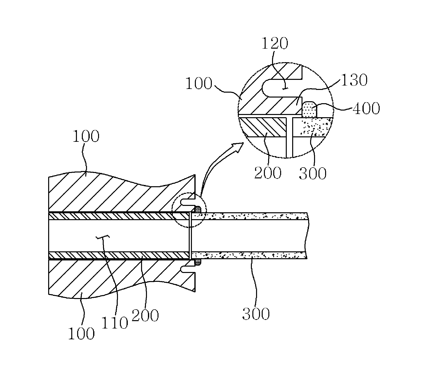
[0034]In a shell and tube welding method in accordance with the present invention, as exemplarily shown in FIGS. 3 to 9, a tube sheet 100 includes tube insertion holes 110, tube sheet grooves 120 and joint parts 130, and a tube joint member 200 and a tube 300 are inserted into the tube insertion hole 110 of the tube sheet 100 and combined with the tube sheet 100 by welding.

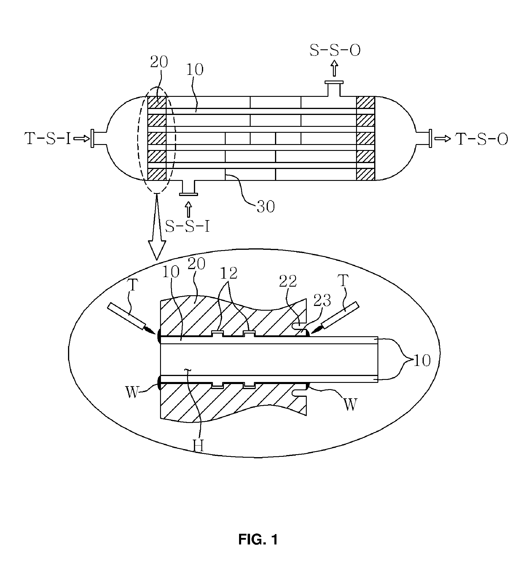
[0035]A shell and tube heat exchanger, to which the shell and tube welding method in accordance with the present invention is applied, is configured such that different fluids are introduced into and discharged from a tube side and a shell side so as to exchange heat with each other, as exemplarily shown in FIG. 3. Since the tubes 300 passing through the inside of the shell side should be completely isolated from the inside of ...


PUM

PropertyMeasurementUnit
Distanceaaaaaaaaaa

Abstract

A method for welding tubes to tube insertion holes formed through tube sheets of a shell and tube heat exchanger, including forming ring-shaped tube sheet grooves, spaced from the tube insertion holes by a designated distance in the outer circumferential direction, on one surface of the tube sheet at the shell side, inserting tube joint members, having a cylindrical shape with the same diameter as that of the tubes, into the tube insertion holes of the tube sheet, manufacturing ring wires by cutting a welding wire having a long length into pieces having a designated length and bending the pieces into a ring shape so as to be inserted into the outer circumferences of the tubes, inserting the ring wire into the outer circumference of one end of the tube, inserting the one end of the tube into the tube sheet in one direction such that the one end of the tube contacts one end of the tube joint member facing the one end of the tube and is located within the recessed distance range of the tube sheet groove, performing tube side welding by welding the other end of the tube joint member to the other surface of the tube sheet at the tube side, and performing shell side welding by inserting a welding torch into the tube joint member and thus welding the one end of the tube joint member, the one end of the tube and the joint part to the one surface of the tube sheet at the shell side using the ring wire as a filler metal.

Description

REFERENCE TO RELATED APPLICATIONS[0001]This application claims the priority benefit of Korean Patent Application No. 10-2015-0047762 filed on Apr. 3, 2015, the entire contents of which are incorporated herein by reference.FIELD OF THE INVENTION[0002]The present invention relates to a shell and tube welding method of a shell and tube heat exchanger.BACKGROUND OF THE INVENTION[0003]A shell and tube heat exchanger includes two tube sheets and a plurality of tubes connecting the tube sheets and is configured to be enclosed by a cylindrical body, i.e., a shell. The shell and tube heat exchanger is used in various types of heat exchange, such as heating, cooling, condensation, evaporation, etc.[0004]In general, a shell and tube heat exchanger is configured such that different fluids are introduced into and discharged from a tube side and a shell side and the fluid at the tube side and the fluid at the shell side exchange heat, as exemplarily shown in FIG. 1. As a movement path of the flui...

Claims


Application Information

Patent Timeline
IPC IPC(8): B23K11/093
CPCB23K2201/14B23K11/0935B23K31/02B23K2101/14B23K9/0284B23K9/0288F28F9/18F28F9/185F28D7/16F28F9/013
Inventor YOO, YONG HYUNLEE, KANG JUNPARK, SHIN GHUJU, JEONG CHEOLOH, JEONG SEOKPARK, YOU JIN
Owner SEWON CELLONTECH CO LTD
Why Eureka
Try Eureka