Eureka AIR delivers breakthrough ideas for toughest innovation challenges, trusted by R&D personnel around the world.

Method for grinding wafers by shaping resilient chuck covering

Inactive Publication Date: 2016-10-06
STRASBAUGH
View PDF0 Cites 3 Cited by
  • Summary
  • Abstract
  • Description
  • Claims
  • Application Information

AI Technical Summary

Benefits of technology

The patent describes a method of improving the first side of a substrate by using a resilient back-grind tape that is attached to a ceramic chuck using vacuum. The tape is then ground with an abrasive grind wheel to make the surface of the tape parallel to the chuck surface. This process removes any unevenness or bumps in the tape and makes the first side of the substrate smoother, resulting in better grinding and site flatness.

Problems solved by technology

This waviness and sometime highly irregular wafer shape after sawing presents subsequent difficulties especially for batch processes.
Although the above-noted patents disclose various techniques for maintaining a uniform wafer thickness, the total thickness (TTV) variation is too high to meet the requirements of new chip technology.

Method used


Image

  • Method for grinding wafers by shaping resilient chuck covering
  • Method for grinding wafers by shaping resilient chuck covering
  • Method for grinding wafers by shaping resilient chuck covering

Examples


Embodiment Construction

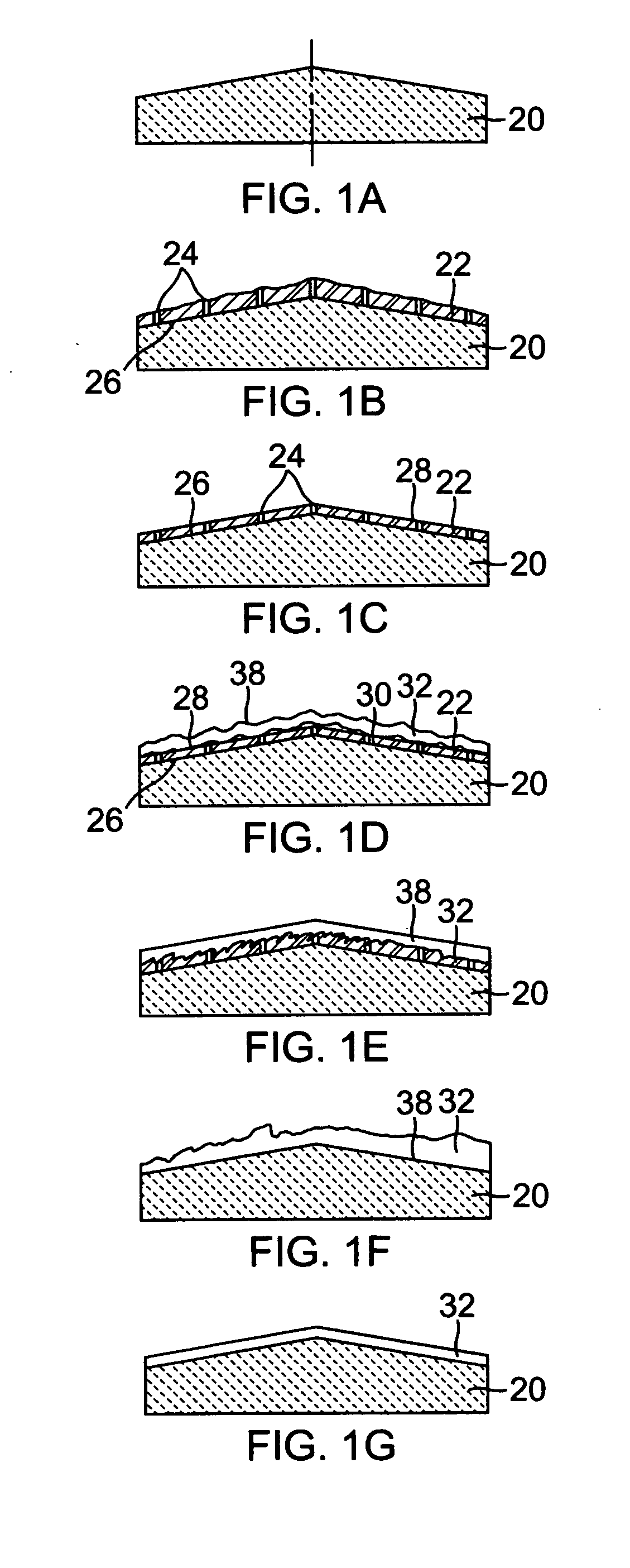
[0017]Referring to FIGS. 1(a)-1(g), the steps of grinding the wafer in accordance with the teachings of the present invention is illustrated.

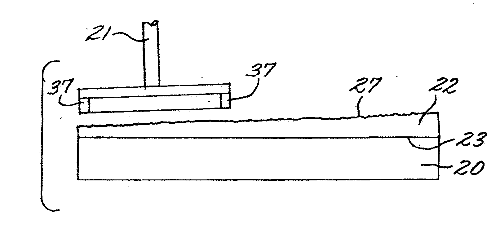
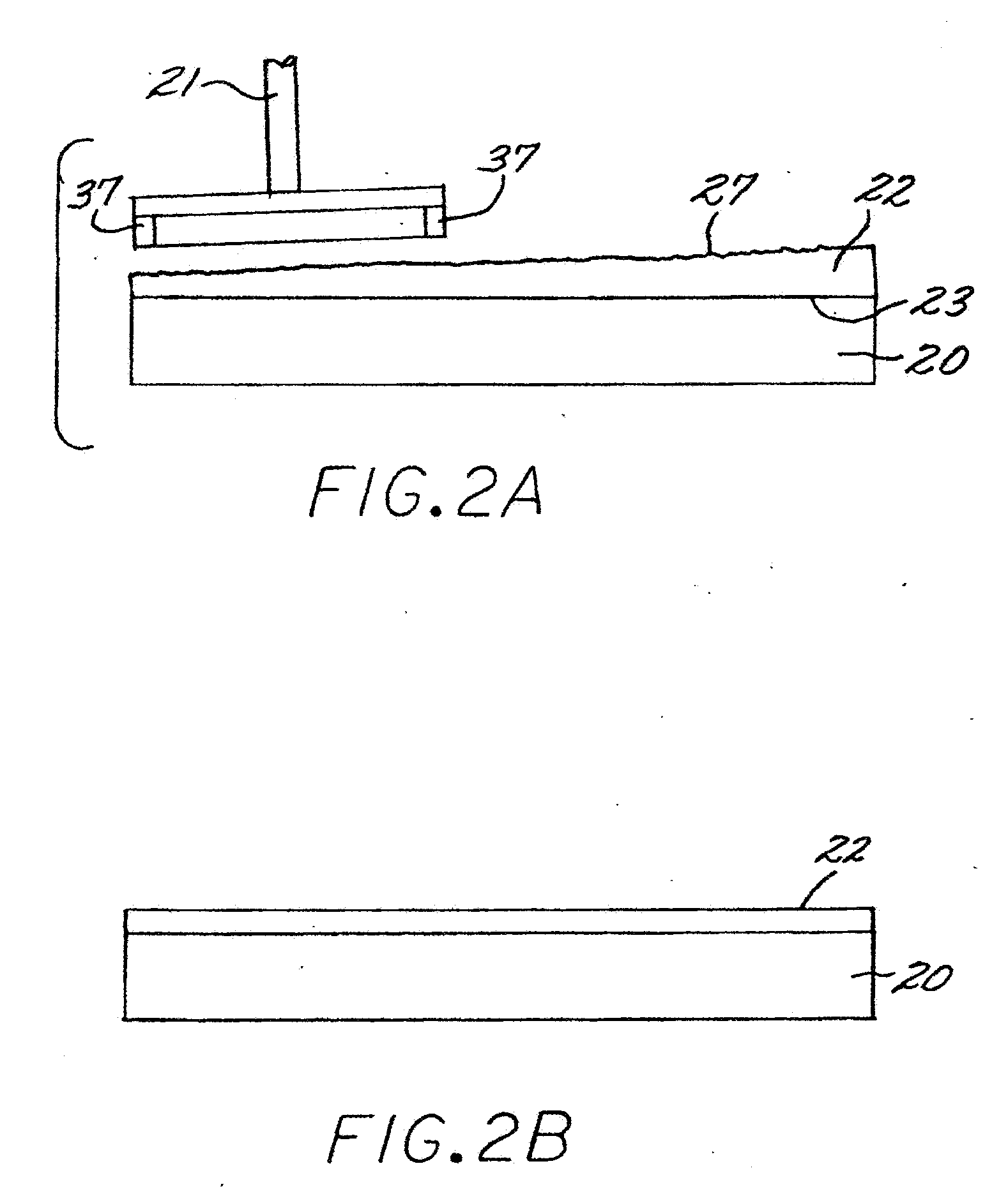
[0018]A porous ceramic chuck 20 is first ground to the desired shape (FIG. 1A) and then a flexible tape 22 with holes 24 formed therein is placed on the top surface 26 of chuck 20 (FIG. 1B). The area of the tape that interfaces with surface 26 is referred to as the “soft” chuck surface. FIG. 2A illustrates, in simplified form, when tape 22 is first applied to chuck 20.

[0019]The upper surface 28 of tape 22 is then ground by grinder 21 parallel to surface 26 (FIG. 1C). The bottom surface 30 of wafer 32 (shown to have a wavy shape) is then positioned in contact with the upper surface 28 of tape 22 and a vacuum is applied through holes 24 to secure wafer 32 to tape 22 (FIG. 1d). Surface 38 of wafer 32 is then ground (FIGS. 1d and 1e) producing a wafer with a surface parallel to the chuck top surface 26. The wafer is then removed from the tape and t...


PUM


Abstract

A method for facilitating and improving the production of quality thin wafers by adhering traditional resilient back-grind tape that has been perforated over the area that will contact the wafer on the ceramic porous grind chuck, so as to allow a vacuum to be applied to the wafer back surface to hold the wafer for processing. The tape adhering to a first surface of the chuck is ground with an abrasive grind wheel, bringing the surface of the tape parallel to the chuck surface which was previously ground by the same grinding device. The wafer is then flipped over and placed on the chuck, the second surface of the wafer then being ground. Grinding the tape while it is mounted on the chuck establishes the plane perpendicular to the grind wheel spindle, removes the bumpiness from the perforation holes and evens out the non-uniformity of the tape, resulting in improved wafer back side grinding and thus good site flatness.

Description

RELATED APPLICATIONS[0001]This application is a continuation-in-part of application Ser. No. 13 / 573,148, filed Aug. 27, 2012.BACKGROUND OF THE INVENTION[0002]1. Field of the Invention[0003]The present invention is utilized in the manufacture of semiconductor material wafers without components on the front side and in particular, a method and apparatus for preventing the wafer from distorting during the planarization steps by attaching a grindable resilient tape to a porous grind chuck or hard chuck with discrete vacuum holes, grinding the tape and then placing a wafer on the chuck for processing.[0004]2. Description of the Prior Art[0005]The semiconductor industry has, and is, interested in producing material wafers with very low total thickness variation (TTV) from wafers that are uneven in thickness, post wire sawing for example. Most wafers are cut from their growth boule using a high production wire-sawing method that inherently produce waviness and high TTV due to the irregular...

Claims


Application Information

Patent Timeline
IPC IPC(8): B24B37/30B24B37/04H01L21/304B24B7/22
CPCB24B37/30H01L21/304B24B37/042B24B7/228H01L21/02013
Inventor KASSIR, SALMAN M.
Owner STRASBAUGH
Why Eureka
Eureka Blog
Learn More