Mixed Flow Fan Assembly

a fan assembly and mixed flow technology, applied in the direction of machines/engines, mechanical equipment, liquid fuel engines, etc., can solve the problems of reducing the efficiency of recirculation, consuming available energy, and reducing the total flow capacity of the impeller, so as to facilitate the mounting of blades or contours, enhance the cooling effect, and increase the volumetric flow rate

Active Publication Date: 2016-10-06
DYNA TECH SALES CORP
View PDF1 Cites 11 Cited by
  • Summary
  • Abstract
  • Description
  • Claims
  • Application Information

AI Technical Summary

Benefits of technology

[0023]The present invention modifies the standard design of a mixed flow fan in five ways: (1) An optimized impeller cone plate design is offered that creates sufficient pressure gradients when the impeller is rotating so as to draw fresh ambient air through a multi-purpose port in the fan housing, over a direct drive fan motor, and down into the fan wheel shroud through an aperture at the common centerline. An optional impeller back plate can be included to facilitate the mounting of blades or contours to enhance this cooling effect. This ambient air flow serves three purposes: (a) cooling the fan drive assembly, which is comprised of a motor for direct drive applications or a set of shafts and bearings for belt drive applications, as well as a variable frequency drive (VFD), if present; (b) maintaining positive pressure in the motor enclosure so as to segregate it from potentially contaminated primary exhaust flowing through the annular space around it; (c) diluting the primary effluent and increasing the volumetric flow rate of air / gas exiting the fan discharge, thereby increasing static efficiency.
[0024](2) One or more openings are provided in the base of the fan housing or between the fan housing and the plenum or roof curb on which it is mounted. Fresh ambient air is induced through the opening(s) by the venturi effect of the primary exhaust exiting the fan wheel / impeller shroud. This induced air flow will enter the area surrounding the impeller shroud and the inlet bell and balance the low pressure generated in this region by the increased velocity of the primary exhaust exiting the impeller shroud. Otherwise, this low pressure region will draw some of the primary exhaust from the impeller shroud OD back down below the impeller shroud ID, causing recirculation of a portion of the primary exhaust airstream and consequent loss of efficiency. This recirculation can be characterized by flow discharging the impeller and re-entering the impeller ID to be re-processed and / or flow that discharges the impeller and continues to rotate in the interstitial space between the fan housing interior and the inlet bell exterior. The optimized pressure gradients resulting from the geometry of the present invention serve to minimize primary exhaust recirculation and provide a means to induce fresh ambient air, thereby increasing the overall volumetric flow rate to produce a greater static efficiency per unit input power.
[0025](3) Impeller blades (flights) are designed with airfoil profiles, with an overlap of substrate at the trailing edge creating a single-thickness trailing edge, which can be shaped and / or perforated to reduce operational fan noise.
[0026](4) In order to axially redirect the radial and tangential velocity vectors of the primary exhaust leaving the fan wheel shroud, full length straightening guide vanes are provided in the annular exhaust plenum within the fan housing. Each guide vane transitions from a curved leading edge to a substantially axial trailing edge, thereby transitioning the primary airflow to an axial flow as it exits the fan housing. This reorientation of the primary airflow velocity minimizes turbulence and rotational vortices in the annular exhaust plenum, resulting in a greater volumetric flow rate and increased overall static efficiency of the fan assembly.
[0027](5) The present invention modifies the shroud angle, positioning of the flights, cone plate geometry, inlet bell geometry, and various offsets to minimize exhaust gas recirculation. The geometry serves to optimize dynamic head and static pressure gradients throughout the path taken by the airflow(s). The result is a reduction in the potential for some of the primary airflow to discharge the impeller and recirculate around the rotating impeller shroud and back through the impeller offset to be reprocessed by the impeller, and / or rotate in the direction of the impeller rotation in the space between the exterior of the inlet bell and interior of the fan housing (in polar coordinates defined as a continued rotation about a given angle at a given radius from the fan centerline). The reduction / elimination of recirculated primary air flow improves the fan's ability to use mechanical energy to move a given volume of air and improves efficiency. The impeller discharge containment region, created when the flight training edge of each impeller flight is recessed a prescribed distance from the impeller cone plate OD edge and the impeller shroud OD edge, provides the necessary space within the impeller shroud for the flow to develop as it exits the rotating impeller, thus minimizing the need for an extended space between the impeller cone plate OD edge and the bottom of the guide vanes section. By providing the impeller discharge containment region upstream of the guide vane area, the guide vanes can be moved closer to the rotating impeller, so as to optimize the effect of the guide vanes in axially redirecting the air flow discharged from the impeller. With the end of the guide vanes section being coterminous with the fan discharge, the guide vane length is maximized. The guide vanes can then do a more effective job of minimizing rotational flow, characterized by energy consuming vortices and turbulence, in the annular exhaust plenum. Since the energy expended in the annular exhaust plenum is minimized, more energy can be used to process primary air in the present invention than in prior art, leading to a comparably greater efficiency.

Problems solved by technology

This recirculation reduces efficiency by reducing the total flow capacity of the impeller by the portion of airflow that is recirculated by the impeller.
While there must be adequate space between the bottom of the guide vanes and the trailing edge of the impeller blades to allow the airflow to develop as it discharges the rotating impeller, too much separation between the guide vanes and the impeller discharge leads to highly rotational flow and the development of vortices / turbulence in the annular exhaust plenum, which consumes available energy and reduces overall efficiency.

Method used


Image

  • Mixed Flow Fan Assembly
  • Mixed Flow Fan Assembly
  • Mixed Flow Fan Assembly

Examples


Embodiment Construction

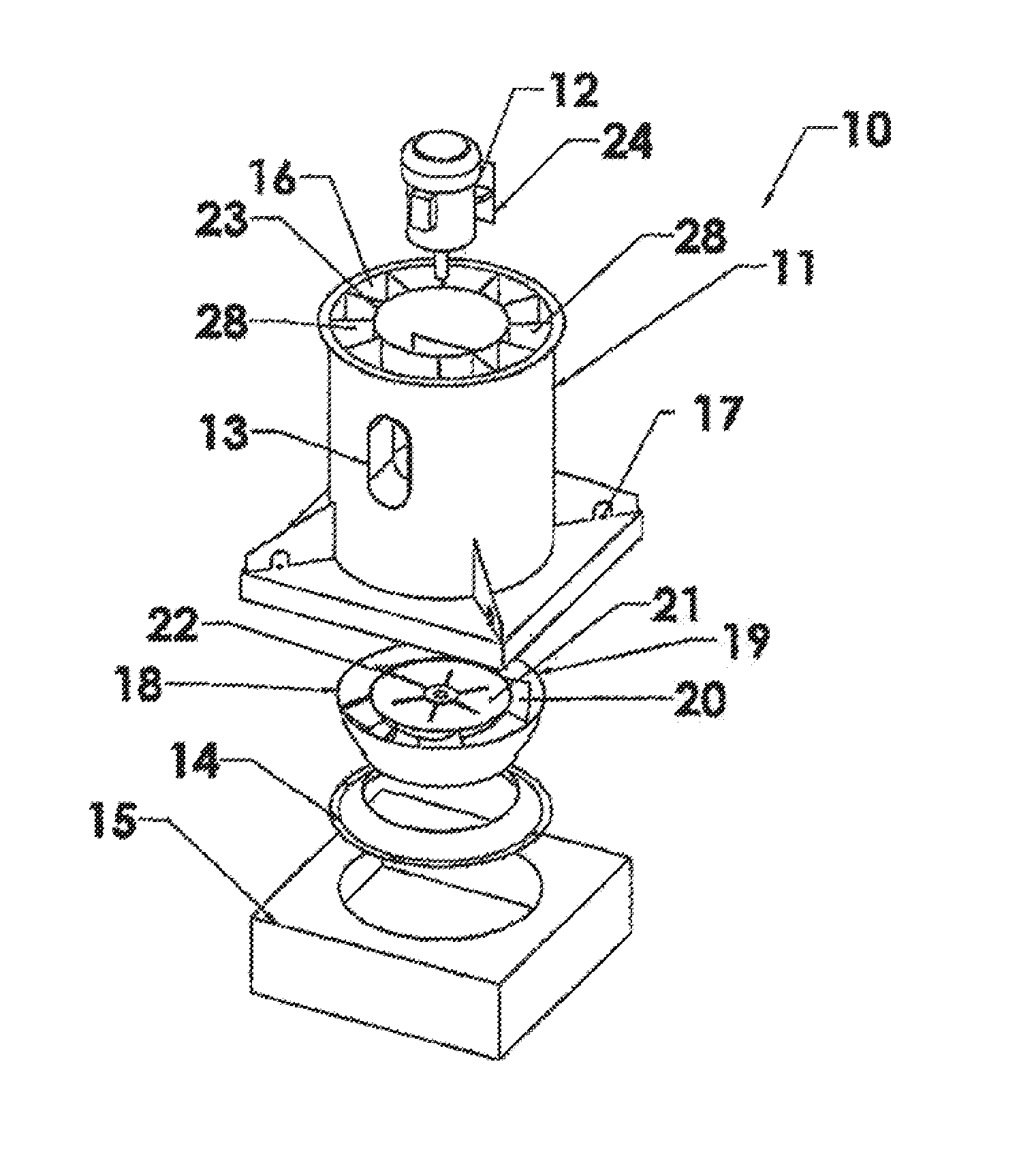
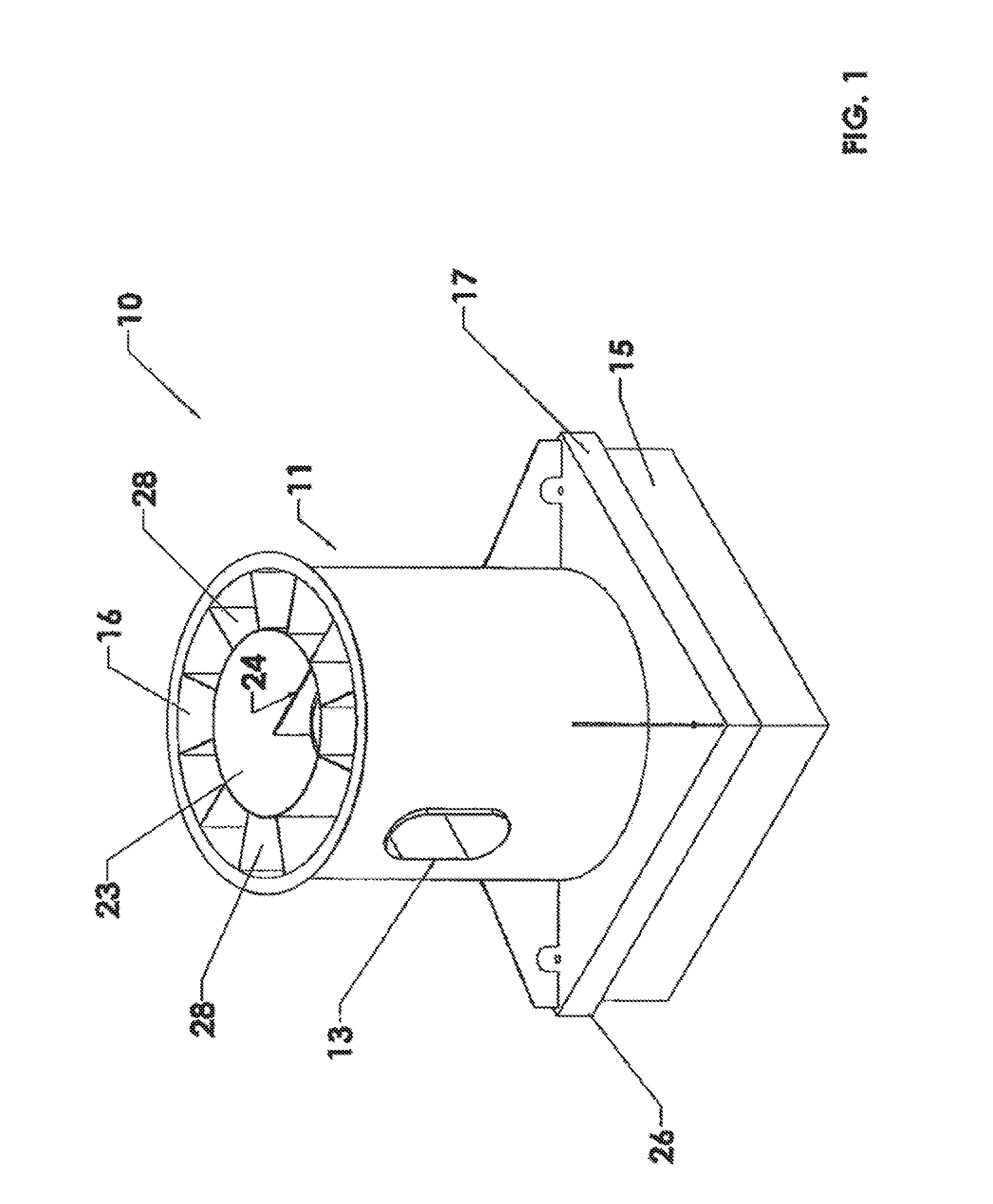
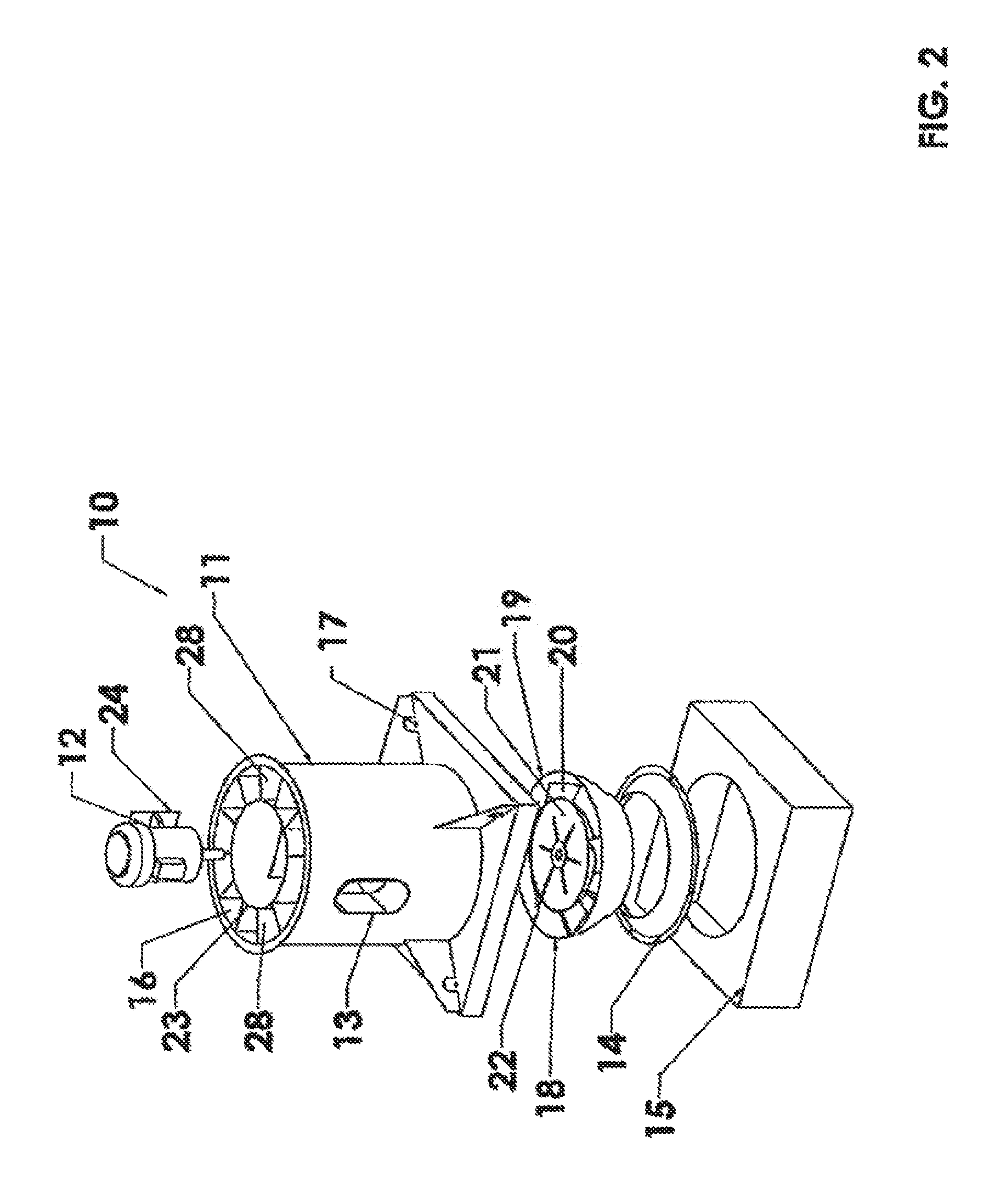
[0045]Referring to FIGS. 1-5B and FIGS. 12-14, an embodiment of a mixed flow fan assembly according to the present invention 10 comprises a cylindrical fan housing 11, the base 17 of which is supported on a mounting plenum (curb) 15. The perimeter of the fan housing base (curb cap) 17 is oversized with respect to that of the mounting plenum 15, so as to leave a peripheral base opening 26, through which ambient air can enter the fan housing 11.

[0046]The upper portion of the fan housing 11 is internally divided into an axially central cylindrical motor enclosure 23 surrounded by an annular cylindrical exhaust plenum 16. The motor enclosure 23 contains an in-line fan motor 12, which is mounted on a vertical mounting plate 24, thereby enabling the bottom of the motor enclosure 25 to remain open. A multi-purpose port 13 accesses the interior of the motor enclosure 23 through the exterior of the fan housing 11 and the exhaust plenum 16.

[0047]In the lower portion of the fan housing 11 belo...


PUM


Abstract

A mixed flow fan assembly uses induced reverse ambient air flow through the in-line motor enclosure for motor cooling, motor segregation from primary exhaust contamination, and augmentation of volumetric flow rate. Induced ambient airflow through openings in and/or around the base of the fan housing balances low pressure around the fan wheel and the inlet cone to inhibit primary exhaust recirculation and increase volumetric flow rate. Guide vanes downstream of the fan wheel are used to axially reorient radial and tangential velocity components of primary effluent flow. The geometry of the fan assembly is optimized to minimize exhaust gas recirculation and maximize overall efficiency.

Description

REFERENCE TO RELATED APPLICATION[0001]This application is a continuation-in-part of U.S. application Ser. No. 14 / 062,311, filed Oct. 24, 2013, the disclosure of which is incorporated herein by reference.BACKGROUND OF THE INVENTION[0002]The present invention relates to the general field of inline exhaust fan assemblies, and more particularly to mixed flow fan assemblies.[0003]In a mixed flow fan assembly, the primary exhaust gas / air flow enters the impeller axially, i.e., parallel to the impeller shaft axis, and is discharged from the impeller with both axial and radial velocity components. The objective of the present invention is to provide a mixed flow fan assembly with greater static efficiency and reduced noise output, thereby reducing the energy required to run the fan at an equivalent performance level. The fan assembly described herein is designed to operate upstream of a discharge nozzle, such as the induction nozzle described in U.S. patent application Ser. No. 13 / 067,269, ...

Claims


Application Information

Patent Timeline
Patent Type & Authority Applications(United States)
IPC IPC(8): F04D25/08F04D29/38F04D27/00F04D29/52F04D29/58F04D25/06F04D29/32F04D29/54
CPCF04D25/082F04D29/326F04D29/384F04D27/004F04D29/522F04D29/5806F04D25/06F04D29/542F04D17/06F04D29/4213F04D29/441F05D2250/51F04D29/4226F05D2240/304F04D29/544F04D29/444
Inventor MORNAN, BRIAN J.BEITZ, FRANK J.ALMERINI, NICHOLAS J.
Owner DYNA TECH SALES CORP
Why Eureka
Try Eureka