System and Method for Unloading Compressed Natural Gas

a compressed natural gas and system technology, applied in the direction of container discharging methods, container filling under pressure, vessel construction details, etc., can solve the problems of affecting the economics of pressurized gas transportation and delivery, pressure, temperature and flow rate can drop even lower, and the operation difficulty of unloading compressed natural gas from transport tanks is often encountered, so as to improve the efficiency of gas transportation, reduce the residual gas pressure, and facilitate the effect of delivery and installation

Inactive Publication Date: 2016-10-06
DIGGINS DAVID A
View PDF42 Cites 34 Cited by
  • Summary
  • Abstract
  • Description
  • Claims
  • Application Information

AI Technical Summary

Benefits of technology

[0011]In another embodiment of the invention, a natural gas pressure reduction system of the invention is configured as a skid mounted unit that can be conveniently delivered and installed at a preferred, possibly temporary location, quickly put into service, and then relocated to another use site when desired. Such a skid-mounted unit is desirably located at or nearby a CNG unloading site and comprises heat exchangers, automated flow control valves, a heat exchange medium and recirculation system, a heat source for the recirculated heat exchange medium, piping, instrumentation and controls needed to receive highly pressurized CNG from a transport tank and discharge it into the receiving lines of an industrial user. The automated flow control valves desirably include stem-guided, high pressure control valves (as marketed, for example, by Kimray Inc.). Such valves are automated in that they are “self-trimming” in response to the sensed downstream pressure. A digital control system, preferably including a programmable logic controller (“PLC”) or functional equivalent, is desirably provided to regulate the flow rate and temperature of the heat exchange medium within the heat exchange recirculation system of the invention by controlling operation of a heater and recirculation pump. The subject system differs from prior closed-loop regulators in that the heat source desirably utilizes the same gas being unloaded to reheat gas that has undergone the pressure drop and associated cooling upon being discharged from the transport. Collectively, the automated flow control valves and the heat exchange medium recirculation system are desirably configured to enable the system to achieve lower residual gas pressures (“abandonment pressures”) in the gas transport, thereby improving the efficiency of the gas transport and delivery process.

Problems solved by technology

Using conventional unloading systems, operational difficulties are often encountered in unloading CNG from transport tanks into pipelines or during delivery to other industrial customers, particularly when ambient temperatures are well below standard conditions.
The economics of pressurized gas transport and delivery are also adversely affected if the amount of gas delivered is insufficient to reduce the residual pressure in the transport vessel to a desired minimum level for return to a gas-loading site.
As the remaining lower-pressure gas passes through the valve, the pressure, temperature and flow rate can drop even lower, to undesirably low levels, especially when the ambient temperatures are low as well.
In some cases, this can require increasing the flow rate through the discharge line of the delivery system at the same time that the flow rate in the delivery system is being depleted as the transport tank is emptied, which in turn further cools the temperature of the gas discharged through the throttling valves.
Also, when the pressure differential across the throttling valve falls to a level where a significant volume of lower-pressure gas remains inside the tank and cannot be discharged at the required minimum temperature and pressure.
The natural gas transporter is then faced with the problem of having to transport a significant volume of gas back to the reloading station, thereby incurring additional transportation charges for a portion of the original natural gas payload that was not deliverable.

Method used


Image

  • System and Method for Unloading Compressed Natural Gas
  • System and Method for Unloading Compressed Natural Gas

Examples


Embodiment Construction

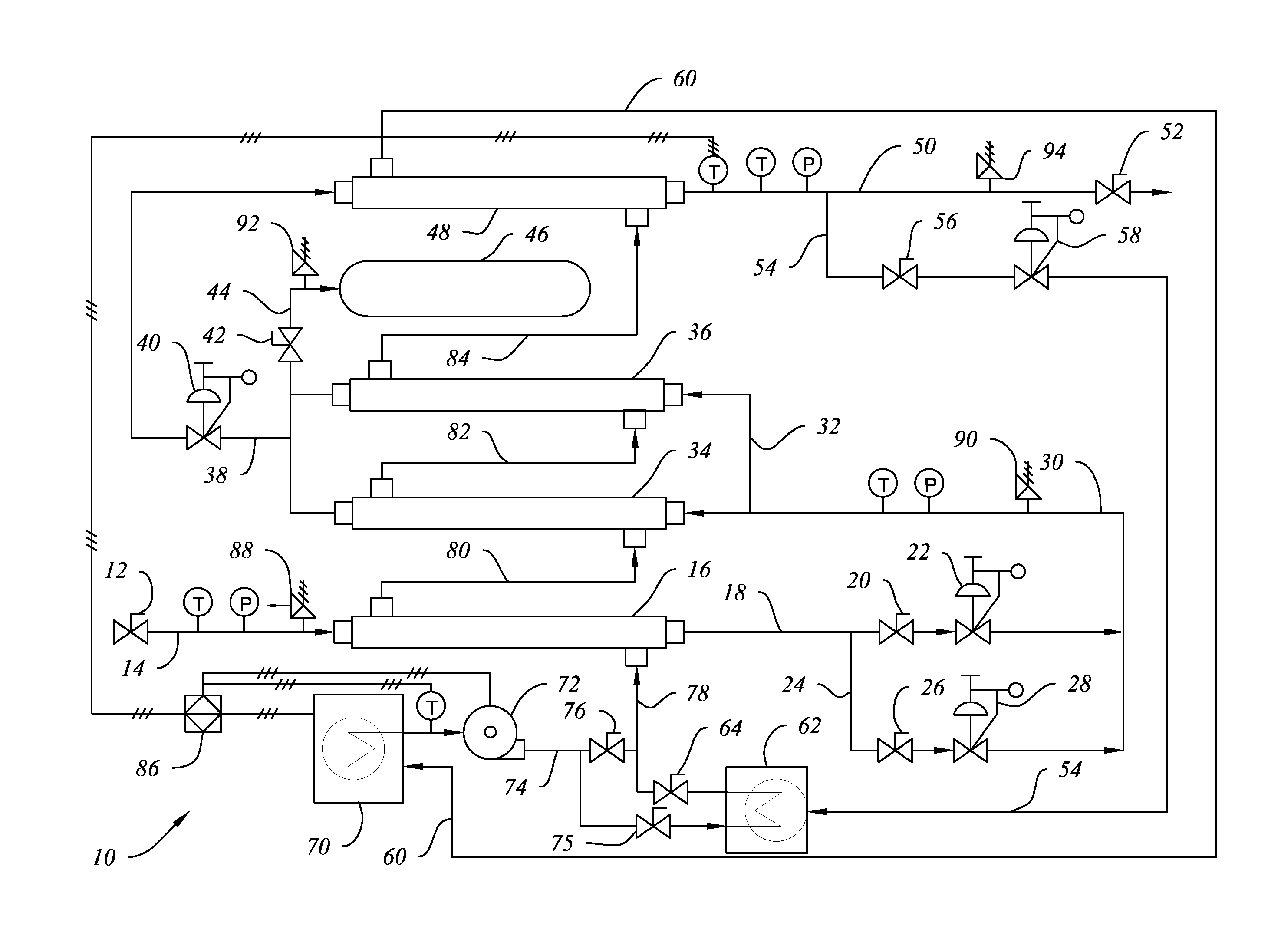
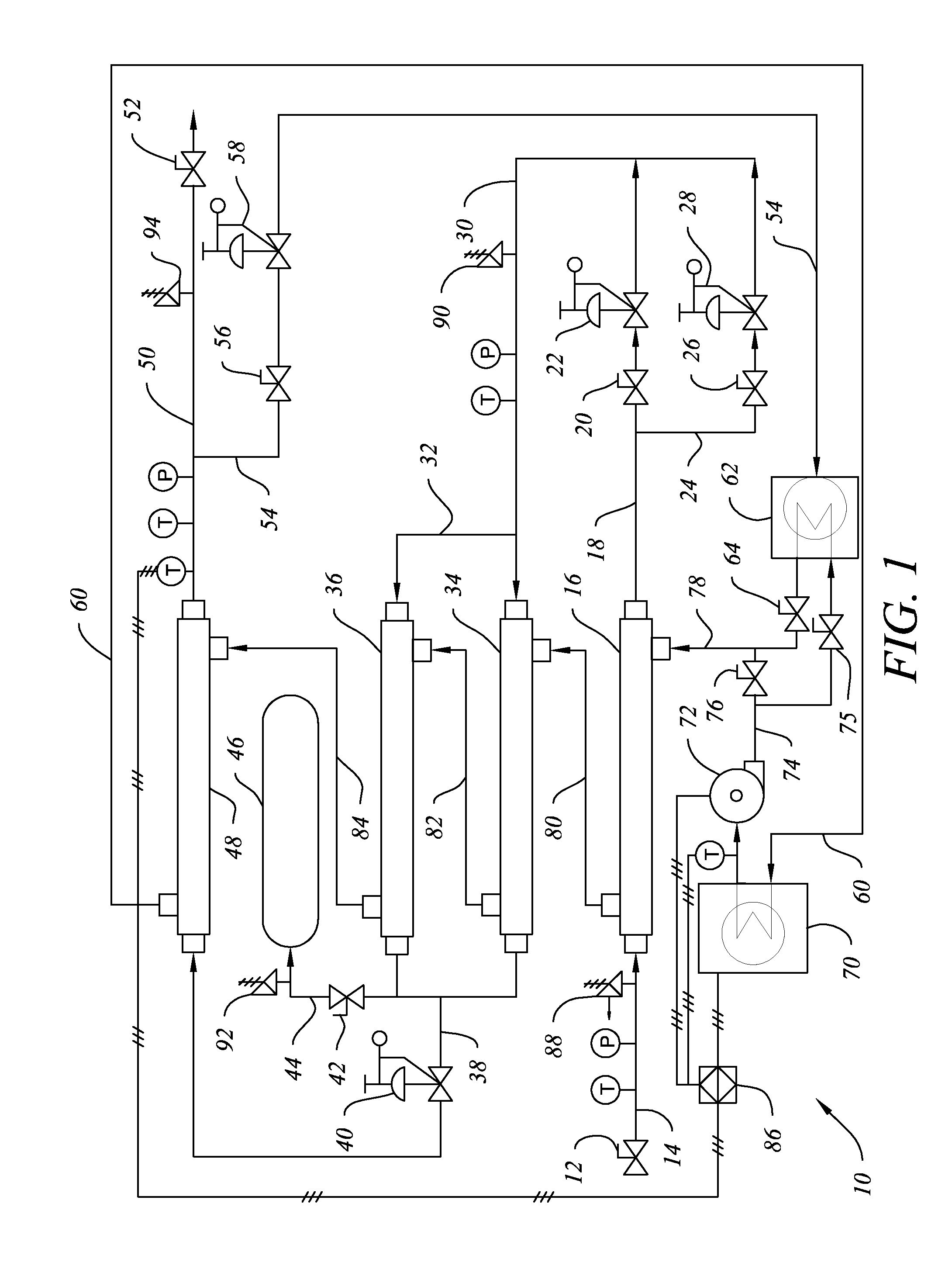
[0014]System 10 and the method of the invention are further disclosed in relation to FIG. 1 of the drawings. Compressed natural gas (“CNG”) is received into system 10 through inlet valve 12 in flow line 14 at a transport pressure of about 3000 to about 4200 PSI. Pressure relief valve 88 is disposed between inlet valve 12 and heat exchanger 16 to protect system 10 from any gas source in which the gas pressure exceeds the maximum operational pressure for which system 10 is designed, such as, for example, about 4500 PSI. Heat exchanger 16 is desirably a shell and tube heat exchanger designed for use at pressures exceeding the operational pressures disclosed above.

[0015]The CNG is desirably heated to about 105° F. in heat exchanger 16 and, upon exiting the heat exchanger, passes through flow lines 18, 24 and valves 20, 26 to be throttled from the inlet pressure to an intermediate pressure of 300 PSI in one or more automated flow control valves 22, 28. The number of throttle valves is de...


PUM


Abstract

A system and method for unloading highly pressurized compressed natural gas from transport vessels by depressurizing the gas through flow lines linking a series of automated flow control valves that lower the gas pressure to a predetermined level, the valves being linked in series with and separated by heat exchangers in which the lower pressure gas flowing through the system is also reheated to a predetermined temperature by a heat exchange medium recirculation system in which the heat exchange medium is reheated by a heat source that can be internal to the system. The use of a minor portion of the depressurized and reheated gas as fuel gas to reheat the heat exchange medium is also disclosed. The subject system can be skid-mounted if desired.

Description

1. FIELD OF THE INVENTION[0001]The subject invention relates to a system and method for unloading pressurized gas, preferably compressed natural gas (“CNG”), from transport tanks in which it is delivered from a source such as a wellhead storage tank to a destination such as a customer, industrial user, or pipeline. More particularly, the invention relates to a system and method for unloading and depressurizing compressed natural gas while automatically controlling the temperature, pressure and flow rate of the delivered gas within acceptable ranges. Another aspect of the invention relates to a system and method for reducing residual gas pressure in a transport tank to a desired minimal level when unloading compressed natural gas. Still another aspect of the invention relates to a method for unloading compressed natural gas that includes diverting a minor portion of the offloaded gas that is discharged from the system of the invention following depressurization for use as low pressur...

Claims


Application Information

Patent Timeline
Patent Type & Authority Applications(United States)
IPC IPC(8): F17C7/02
CPCF17C2227/03F17C7/02F17C5/06F17C7/00F17C2205/0332F17C2205/0338F17C2221/033F17C2223/0123F17C2223/035F17C2223/036F17C2225/0123F17C2225/033F17C2227/0316F17C2227/0323F17C2227/0332F17C2250/01F17C2250/043F17C2250/0439F17C2250/0631F17C2260/056F17C2270/0134F17C2270/0142F17C2270/05
Inventor DIGGINS, DAVID A.
Owner DIGGINS DAVID A
Why Eureka
Try Eureka