
Method, Apparatus and Substrates for Lithographic Metrology

Active Publication Date: 2016-10-06
ASML NETHERLANDS BV
View PDF3 Cites 32 Cited by
  • Summary
  • Abstract
  • Description
  • Claims
  • Application Information

AI Technical Summary

Benefits of technology

The patent is about a way to measure how well a mask is aligned with a substrate during a manufacturing process. The method uses target structures and four different values of external bias, which helps to measure the mask accurately even if there are any changes in the shape of the structure. This technique can improve the accuracy and productivity of the manufacturing process.

Problems solved by technology

Although the known dark-field image-based overlay measurements are fast and computationally very simple (once calibrated), they rely on an assumption that overlay is the only cause of asymmetry in the target structure.
This asymmetry which is not related to the overlay clearly perturbs the overlay measurement, giving an inaccurate overlay result.
Accordingly at this time the skilled person has to choose between, on the one hand, a simple and fast measurement process that gives overlay measurements but is subject to inaccuracies when other causes of asymmetry are present, and on the other hand more traditional techniques that are computationally intensive and typically require several measurements of large, underfilled gratings to avoid the pupil image is polluted with signal from the environment of the overlay grating, which hampers the reconstruction on this.

Method used


Image

  • Method, Apparatus and Substrates for Lithographic Metrology
  • Method, Apparatus and Substrates for Lithographic Metrology
  • Method, Apparatus and Substrates for Lithographic Metrology

Examples


Embodiment Construction

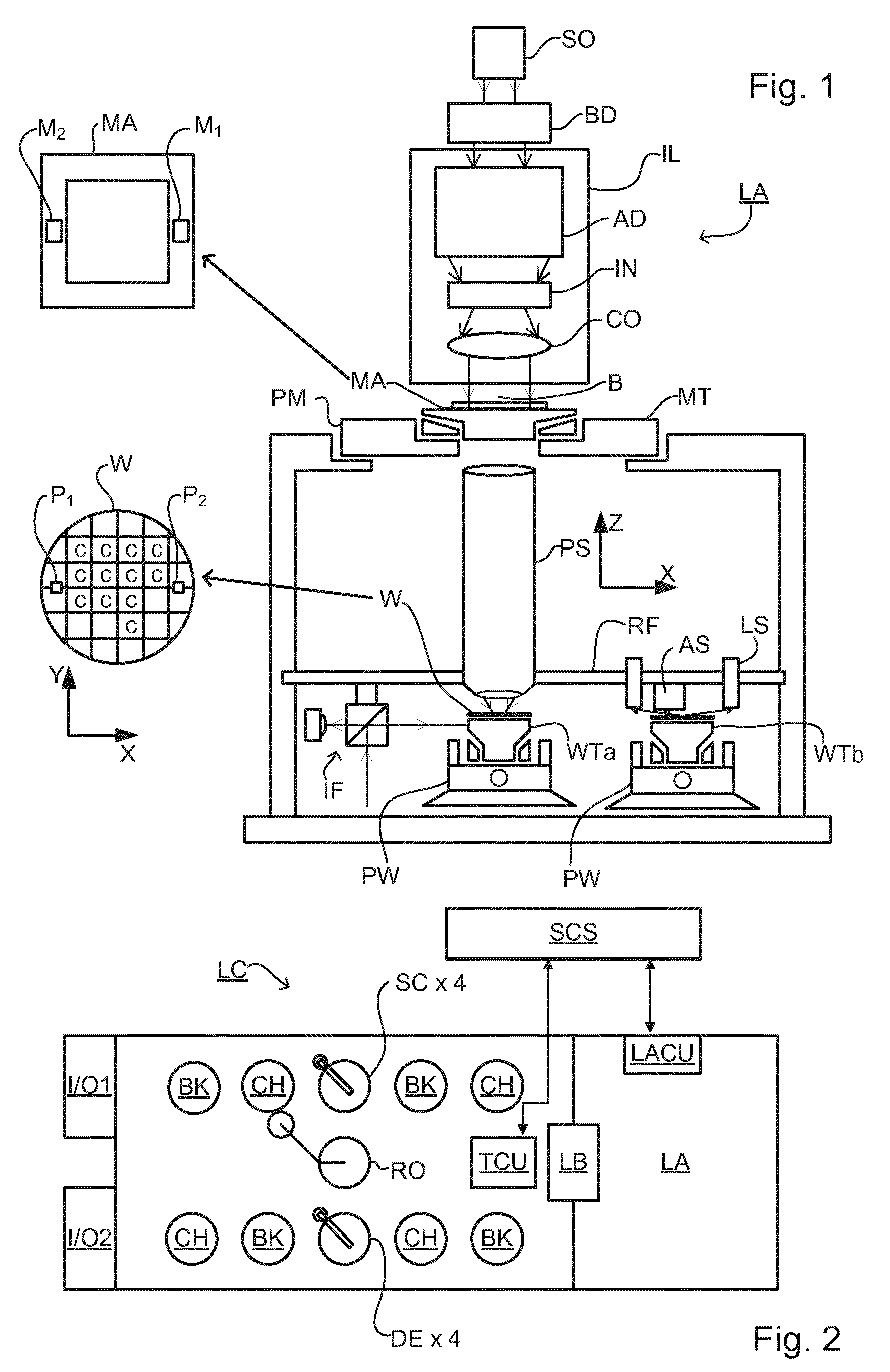
[0054]Before describing embodiments of the invention in detail, it is instructive to present an example environment in which embodiments of the present invention may be implemented.

[0055]FIG. 1 schematically depicts a lithographic apparatus LA. The apparatus includes an illumination system (illuminator) IL configured to condition a radiation beam B (e.g., UV radiation or DUV radiation), a patterning device support or support structure (e.g., a mask table) MT constructed to support a patterning device (e.g., a mask) MA and connected to a first positioner PM configured to accurately position the patterning device in accordance with certain parameters; a substrate table (e.g., a wafer table) WT constructed to hold a substrate (e.g., a resist coated wafer) W and connected to a second positioner PW configured to accurately position the substrate in accordance with certain parameters; and a projection system (e.g., a refractive projection lens system) PS configured to project a pattern im...


PUM


Abstract

A substrate has three or more overlay gratings formed thereon by a lithographic process. Each overlay grating has a known overlay bias. The values of overlay bias include for example two values in a region centered on zero and two values in a region centered on P / 2, where P is the pitch of the gratings. Overlay is calculated from asymmetry measurements for the gratings using knowledge of the different overlay bias values and an assumed non-linear relationship between overlay and target asymmetry, thereby to correct for feature asymmetry. The periodic relationship in the region of zero bias and P / 2 has gradients of opposite sign. The calculation allows said gradients to have different magnitudes as well as opposite sign. The calculation also provides information on feature asymmetry and other processing effects. This information is used to improve subsequent performance of the measurement process, and / or the lithographic process.

Description

CROSS-REFERENCE TO RELATED APPLICATIONS[0001]This application claims the benefit of EP application 13194522, which was filed on Nov. 26, 2013 and which is incorporated herein in its entirety by reference.BACKGROUND[0002]1. Field of the Invention[0003]The present invention relates to methods and apparatus for metrology usable, for example, in the manufacture of devices by lithographic techniques and to methods of manufacturing devices using lithographic techniques.[0004]2. Background Art[0005]A lithographic apparatus is a machine that applies a desired pattern onto a substrate, usually onto a target portion of the substrate. A lithographic apparatus can be used, for example, in the manufacture of integrated circuits (ICs). In that instance, a patterning device, which is alternatively referred to as a mask or a reticle, may be used to generate a circuit pattern to be formed on an individual layer of the IC. This pattern can be transferred onto a target portion (e.g., including part of...

Claims


Application Information

Patent Timeline
IPC IPC(8): G03F7/20
CPCG03F7/70633G03F1/44G03F7/706H01L21/0274H01L22/12
Inventor SMILDE, HENDRIK JAN HIDDEDEN BOEF, ARIE JEFFREYADAM, OMER ABUBAKER OMERJAK, MARTIN JACOBUS JOHAN
Owner ASML NETHERLANDS BV
Learn More