Fuel cell separator and manufacturing method of fuel cell separator
a technology of fuel cell separator and manufacturing method, which is applied in the manufacture of cell components, final product products, electrochemical generators, etc., can solve the problems of deterioration of adhesion, easy oxidation of tic adhesion layer, and difficult to ensure adhesion between titanium base substrate and carbon film, etc., to achieve favorable corrosion resistance and increase the adhesion of carbon film
- Summary
- Abstract
- Description
- Claims
- Application Information
AI Technical Summary
Benefits of technology
Problems solved by technology
Method used
Image
Examples
first embodiment
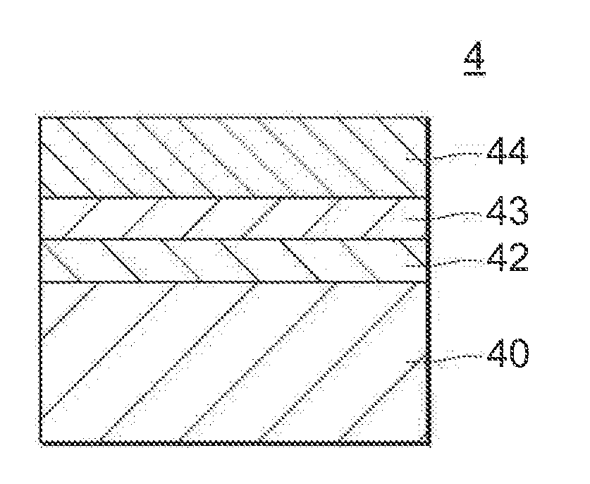
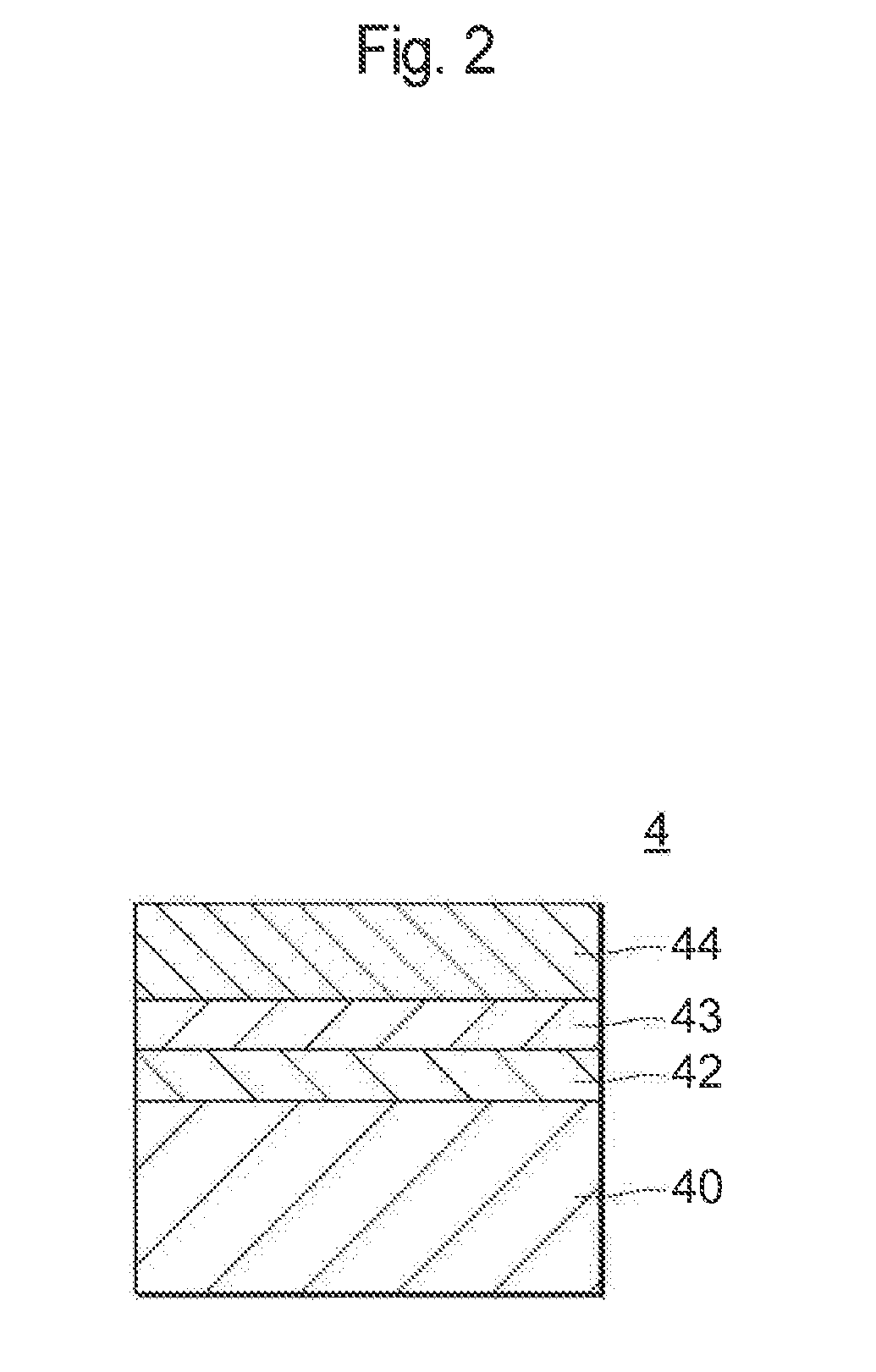
[0033]FIG. 2 is an enlarged cross-sectional view of the separator 4. It should be noted that the cross-section of the separator 5 is the same as that of the separator 4. As shown in FIG. 2, the separator 4 has a titanium base substrate 40, a TiOx (142 formed on the titanium base substrate 40, a carbon film 44 formed on the TiOx layer 42 by plasma CVD and a binder layer 43 including Ti, O and C formed between the TiOx layer 42 and the carbon film 44.
[0034]The titanium base substrate 40 is made of Ti. The thickness thereof is not particularly limited and it may be, for example, 100 μm to 20,000 μm.
[0035]The TiOx (142 is a coating layer formed on the surface layer of Ti and having relatively good corrosion resistance. Due to the presence of TiOx, the separator does not show a particular peak in the potential scanning test simulating a fuel cell environment, and favorable corrosion resistance can be obtained. Furthermore, since the TiOx layer 42 is deficient in oxygen, the TiOx layer 42...
second embodiment
[0053]FIG. 5 is an enlarged cross-sectional view of a separator according to a second embodiment. As shown in FIG. 5, the separator of the second embodiment has a TiO2 layer 41 formed on the titanium base substrate 40, and the TiOx layer 42 is formed on such TiO2 layer 41 and, in this respect, the separator of the second embodiment is different from the first embodiment in which the TiOx layer 42 is formed directly on the titanium base substrate 40. Other than the above, the second embodiment is the same as the first embodiment and the description of the same parts will be omitted here.
[0054]As described before, an oxide layer formed of a TiO2 layer is normally formed on the titanium base substrate 40. In the second embodiment, such oxide layer is not removed but is left remaining as a TiO2 layer 41.
[0055]The manufacturing method of the separator of the second embodiment is different from the manufacturing method of the separator of the first embodiment in steps SP1 and SP2. In the ...
example 1
[0057]A bright-annealed titanium plate was prepared and cut into a piece about 200×400 mm in size to be used as a titanium base substrate 40 (step SP1). Here, bright annealing treatment is a process of burning the titanium plate under a non-oxygen atmosphere, whereby a titanium base substrate 40 having a metal surface of Ti can be obtained. The obtained titanium base substrate 40 was pressed so as to be in the form of a separator, and then cleaned with a hydrocarbon-based cleaning solution and an alkaline cleaning solution (step SP3). After that, acid-pickling treatment was performed with a 50% H2SO4 aqueous solution and the resulting substrate was dried in a vacuum drying oven at 300° C., to thereby form a TiOx layer 42 on the surface of the titanium base substrate 40 (step SP2).
[0058]Subsequently, a carbon film 44 was formed by plasma CVD (step SP4). In the plasma CVD, the titanium base substrate 40 was transferred into a deposition chamber at a temperature of 300° C. and a pressu...
PUM
 Abstract
Description
Claims
Application Information
 - R&D
- Intellectual Property
- Life Sciences
- Materials
- Tech Scout
- Unparalleled Data Quality
- Higher Quality Content
- 60% Fewer Hallucinations
Browse by: Latest US Patents, China's latest patents, Technical Efficacy Thesaurus, Application Domain, Technology Topic, Popular Technical Reports.
© 2025 PatSnap. All rights reserved.Legal|Privacy policy|Modern Slavery Act Transparency Statement|Sitemap|About US| Contact US: help@patsnap.com


