
Low shear process for producing polymer composite fibers

a composite fiber and low shear technology, applied in the field of polymer composite fiber compositions, can solve the problems of filament breakage, limited mechanical properties of final products, and current efforts in the conventional art to improve tensile strength and other characteristics of importance for rapid prototyping, and achieves a high level of tensile strength. , the effect of reducing the amount of filament breakag

Active Publication Date: 2016-10-20
UT BATTELLE LLC
View PDF8 Cites 7 Cited by
  • Summary
  • Abstract
  • Description
  • Claims
  • Application Information

AI Technical Summary

Benefits of technology

This patent is about a new method for making polymer composite fibers. These fibers can be used in rapid prototyping methods and have better strength and smoothness than previous methods. The method uses a low-shear screwless extrusion process, which reduces filament breakage and improves the fiber's strength and uniformity. The resulting fiber has a high level of structural order, which further strengthens it and makes it more uniform in thickness and smoothness. Overall, this method allows for the production of stronger, smoother polymer composite fibers.

Problems solved by technology

However, because only a limited number of materials, such as a limited number of thermoplastics and some engineering plastics, have been used as a feedstock for FFF, the final products generally have limited mechanical properties.
However, a significant problem encountered with the high shear mixing processes of the art, particularly for filamentous particles, is filament breakage, which may occur by, for example, direct contact of the filaments with the screw and by filament-filament grinding.
As the resulting filament breakage significantly undermines the original purpose of including the filament (i.e., improving tensile strength), current efforts in the conventional art for improving tensile strength and other characteristics of importance to rapid prototyping remain deficient.

Method used


Image

  • Low shear process for producing polymer composite fibers
  • Low shear process for producing polymer composite fibers
  • Low shear process for producing polymer composite fibers

Examples


example 1

Fused Filament Fabrication of ABS Matrix Containing Carbon Fibers

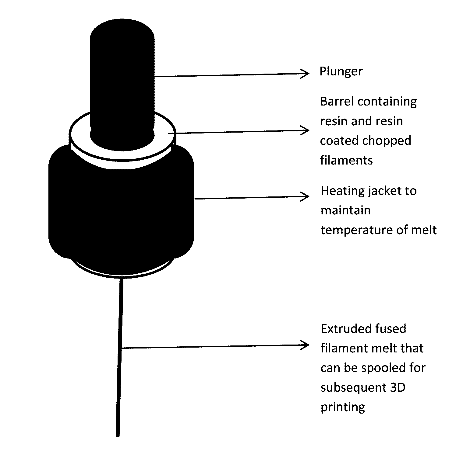
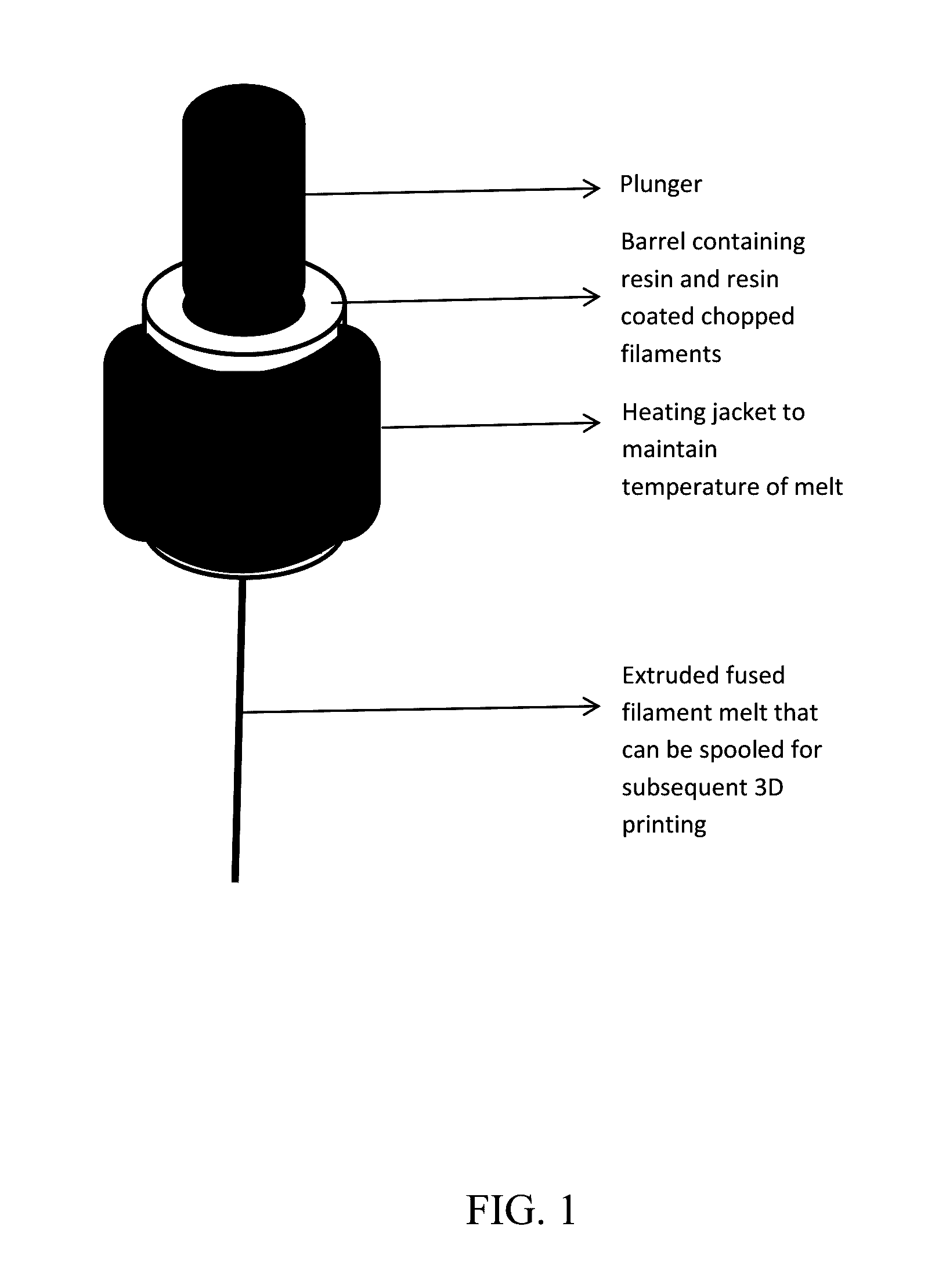
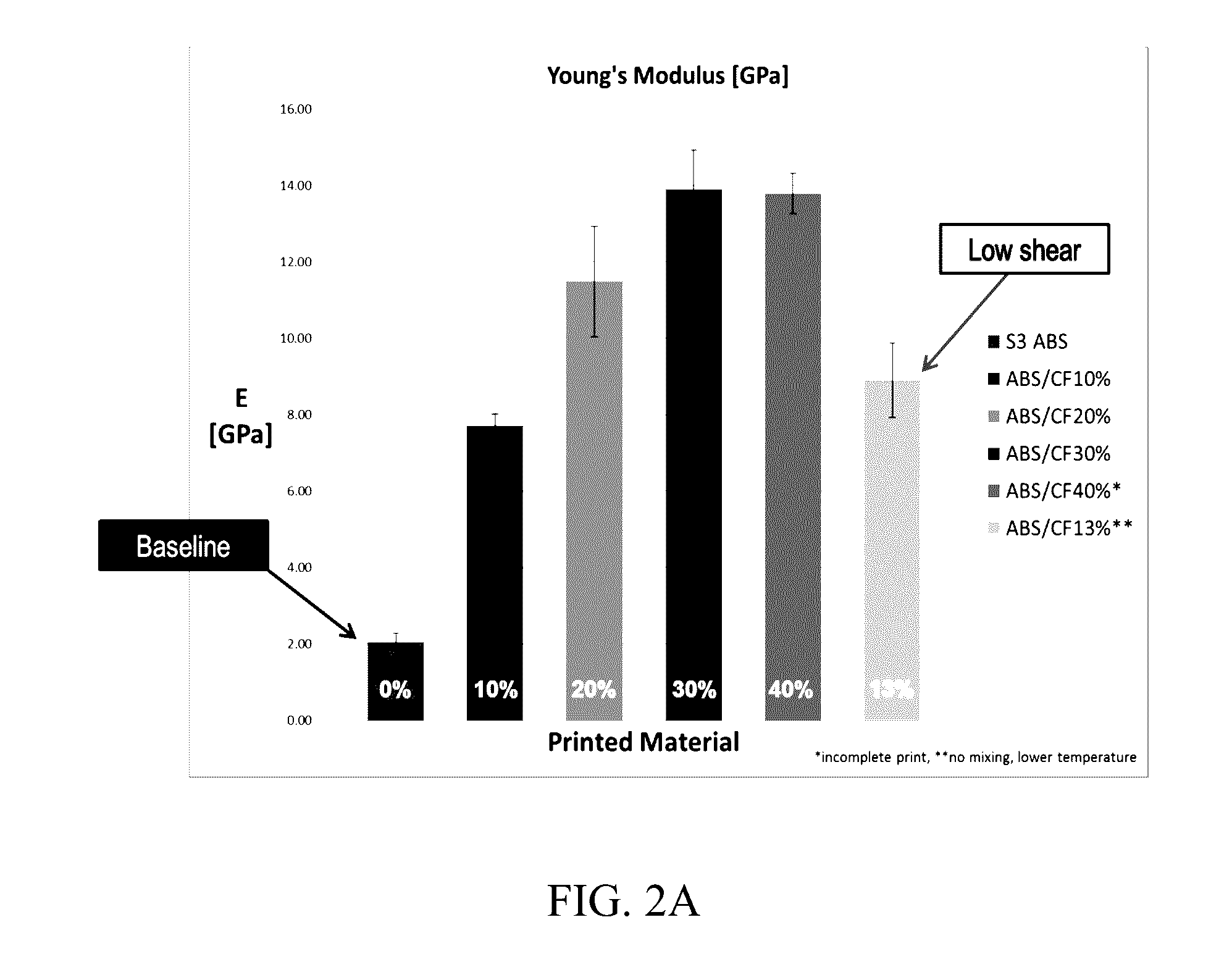
[0032]ABS resin was mixed with various weight fractions (10, 13, 20, 30, 40 wt. %) of carbon fibers, with S3 ABS resin serving as baseline (0 wt. % carbon fiber). Low shear mixing was conducted without the use of a screw. The melt mixed mass was then pushed through a barrel-plunger based low-shear extrusion device at 1 mm / min to 4 mm / min plunger speed. An extruded smooth composite thread was used in the 3D printing, and 3D-printed dog-bones were subsequently tested for their tensile properties.

[0033]The tensile modulus data for the 3D printed parts are shown in FIG. 2A. As shown, with an increase in weight fraction of carbon fiber (CF) loading, the modulus of the printed parts increased. The tensile failure strength data of the specimens are shown in FIG. 2B. It is clear that, with increase in fiber loading, the tensile strength of the composites increased. In particular, FIG. 2B shows that the strength of 40 wt % carb...


PUM

PropertyMeasurementUnit
lengthaaaaaaaaaa
speedaaaaaaaaaa
speedaaaaaaaaaa

Abstract

A method for producing a polymer composite fiber comprised of a polymer matrix with filaments incorporated therein whose lengthwise dimensions are substantially oriented with the axial dimension of the composite fiber, the method comprising subjecting a melt comprised of a polymer matrix and filaments to an extrusion process in which the melt is extruded into a fibrous form in the absence of screw extruders and in the substantial absence of shear forces that result in breakage of the filaments, followed by cooling and solidification of the extruded melt to provide the polymer composite fiber. Integration of these polymer composite fibers with additive manufacturing technologies, particularly rapid prototyping methods, such as FFF and 3D printing, are also described. The resulting polymer composite fibers and articles made thereof are also described.

Description

[0001]This invention was made with government support under Prime Contract No. DE-AC05-00OR22725 awarded by the U.S. Department of Energy. The government has certain rights in the invention.FIELD OF THE INVENTION[0002]The present invention relates generally to polymer composite fiber compositions in which the fiber contains a polymer component and filler particles incorporated therein. The invention more particularly relates to such fiber compositions having characteristics particularly suited for their use in structural applications, such as high tensile strength and structural uniformity. The invention further relates to methods for producing such fiber compositions, and also relates to methods of use for producing various structures, such as by additive manufacturing, or more particularly, rapid prototyping, such as fused deposition modeling (FDM) through fused filament fabrication (FFF)BACKGROUND OF THE INVENTION[0003]Rapid prototyping (RP) is a technology in which a part can be...

Claims


Application Information

Patent Timeline
Patent Type & Authority Applications(United States)
IPC IPC(8): B29C45/00B29C67/00B29C48/49
CPCB29C45/0001B29C67/0081B29K2067/00B29K2069/00B29K2055/02B29L2031/731B29K2025/06B29K2305/00B29K2307/04B29K2081/06B29K2033/20B29C35/02B29K2067/046B32B27/08D06M10/00B29C64/165D06M15/55D01D1/04D01D5/00D01F1/10D06M2101/40B29C48/08B29C48/0018B29C48/21B29C48/022B29C48/49B29C2948/92704B29C2948/92942B29C64/118B29C64/106B33Y70/10
Inventor KUNC, VLASTIMILDUTY, CHAD E.LOVE, LONNIE J.NASKAR, AMIT K.
Owner UT BATTELLE LLC
Learn More