Oscillator circuit

a technology of oscillator and circuit, which is applied in the direction of oscillator generator, pulse automatic control, pulse technique, etc., can solve the problems of increasing the power consumption in idle mode and a long start-up time until, and achieve the effect of reducing the start-up time of the first oscillator

Active Publication Date: 2016-10-20
TELEFON AB LM ERICSSON (PUBL)
View PDF0 Cites 25 Cited by
  • Summary
  • Abstract
  • Description
  • Claims
  • Application Information

AI Technical Summary

Benefits of technology

[0027]The oscillator circuit may comprise an amplitude detector arranged to generate an amplitude signal indicative of an amplitude of the first oscillation signal, and the controller may be arranged to modify a/the duration of the first time period dependent on a time taken for the amplitude signal to reach a target amplitude during the second time period. Likewise, the method may comprise generating an amplitude signal indicative of an amplitude of the first oscillation signal, and modifying a/the duration of the first time period dependent on a time taken for the amplitude signal to reach a target amplitude during the second time period. This feature may enable the start-up time of the first oscillator to be reduced.
[0028]The oscillator circuit may comprise a target count storage device arranged to store a value of a target number of cycles of the second oscillation signal corresponding to the duration of the first time period, and a counter arranged to determine the completion of the first time period by counting the cycles of the second oscillation signal up to the target number during the first time period. Likewise, the method may comprise storing a value of a target number of cycles of the second oscillation signal corresponding to the duration of the first time period, and determining the completion of the first time period by counting the cycles of the second oscillation signal up to the target number during the first

Problems solved by technology

A drawback of crystal oscillators is the relatively long start-up time until the oscillation signal reaches its final amplitude, because crystals oscillators have a high Q-factor, where the Q-factor, also known as the quality fac

Method used


Image

  • Oscillator circuit
  • Oscillator circuit
  • Oscillator circuit

Examples


Embodiment Construction

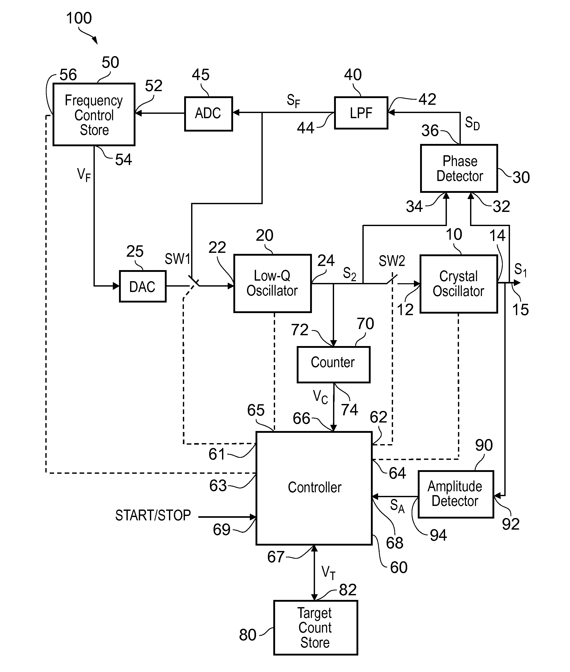
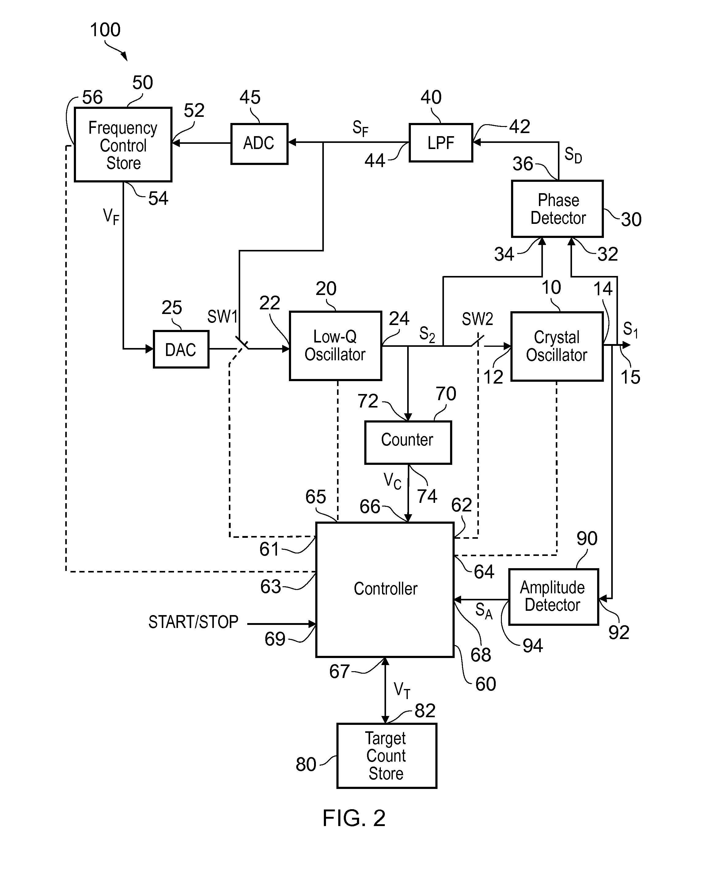
[0006]According to a first aspect there is provided an oscillator circuit comprising:

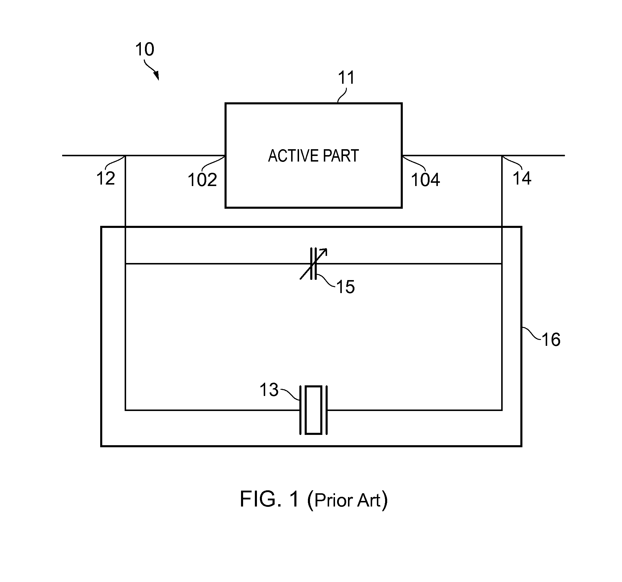
[0007]a first oscillator comprising a crystal and arranged to generate a first oscillation signal at a first frequency, wherein the first oscillator has a first Q-factor;

[0008]a second oscillator arranged to generate a second oscillation signal at a second frequency, wherein the second oscillator has a second Q-factor lower than the first Q-factor;

[0009]a phase detector arranged to generate a difference signal indicative of a phase difference between the first and second oscillation signals;

[0010]a filter arranged to generate a frequency control signal by filtering the difference signal;

[0011]a frequency control storage device arranged to store a value of the frequency control signal;

[0012]a selector switch having selectable first and second selector states, wherein in the first selector state the selector switch is arranged to deliver to a frequency control input of the second oscillator the stored...


PUM


Abstract

An oscillator circuit comprises a first, high-Q crystal oscillator and a second, low-Q oscillator arranged for kick-starting the crystal oscillator at switch-on by coupling the second oscillator to the first oscillator for a time period. The oscillator circuit is arranged to select the frequency of the second oscillator by placing the second oscillator in a phase locked loop with the first oscillator providing a reference frequency, and adjusting the frequency of the second oscillator towards the frequency of the first oscillator.

Description

FIELD OF THE DISCLOSURE[0001]The present disclosure relates to an oscillator circuit, a method of operating an oscillator circuit, and a wireless communication device comprising an oscillator circuit.BACKGROUND TO THE DISCLOSURE[0002]Crystal oscillators are commonly used in electronic systems, for example a mobile phone, to generate highly accurate clock signals. Referring to FIG. 1, a typical crystal oscillator 10 comprises an active part 11, which may be an amplifier, and a tank 16 coupled between an input 102 of the active part 11 and an output 104 of the active part 11. The input 102 of the active part 11 is coupled to a first terminal 12 of the crystal oscillator 10, and an output 104 of the active part 11 is coupled to a second terminal 14 of the crystal oscillator 10. The tank 16 comprises a crystal 13 coupled between the input and output 102, 104 of the active part 11, and a variable capacitor 15 also coupled between the input and output 102, 104 of the active part 11. The v...

Claims


Application Information

Patent Timeline
IPC IPC(8): H03B5/06H03L7/099H03K21/38H03B5/32
CPCH03B5/06H03B5/32H04W88/02H03K21/38H03L7/099H03L3/00
Inventor ELGAARD, CHRISTIAN
Owner TELEFON AB LM ERICSSON (PUBL)
Why Eureka
Try Eureka