
Multiphase generator-conversion systems

a generator and multi-phase technology, applied in wind energy generation, single-network parallel feeding arrangement, electrical equipment, etc., can solve the problems of large amount of components required, overall installation cost, etc., to reduce the weight and size of the transformer, increase the voltage level output of the generator, and reduce noise and harmonics

Active Publication Date: 2016-10-27
GE RENEWABLE TECH WIND BV
View PDF0 Cites 9 Cited by
  • Summary
  • Abstract
  • Description
  • Claims
  • Application Information

AI Technical Summary

Benefits of technology

The patent text describes a system for generating electrical power from multiple wind turbines. The system includes multiple generators, each generating a different phase of electrical voltage. These phases are then combined to create a single electrical current. The system includes a transformer module that increases the output voltage of the generator and reduces the size of the transformer. The text also describes the use of a matrix converter or a first rectification module to directly convert the multi-phase time-varying voltage to a single voltage. This leads to less noise and harmonics and a more standard and cost-effective solution. The use of a second rectification module reduces the number of components, simplifies installation and maintenance requirements, and further reduces the cost of the wind turbine power plant. The second rectification module may be integrated into the wind turbine platform for easy integration.

Problems solved by technology

This conversion may imply a large number of power converters and the necessity of large power transformers.
The large amount of components required is not desirable due to space and weight restrictions of wind turbines, even more so in offshore configurations where transportation, maintenance and servicing raises the overall cost of the installation.

Method used


Image

  • Multiphase generator-conversion systems
  • Multiphase generator-conversion systems
  • Multiphase generator-conversion systems

Examples


Embodiment Construction

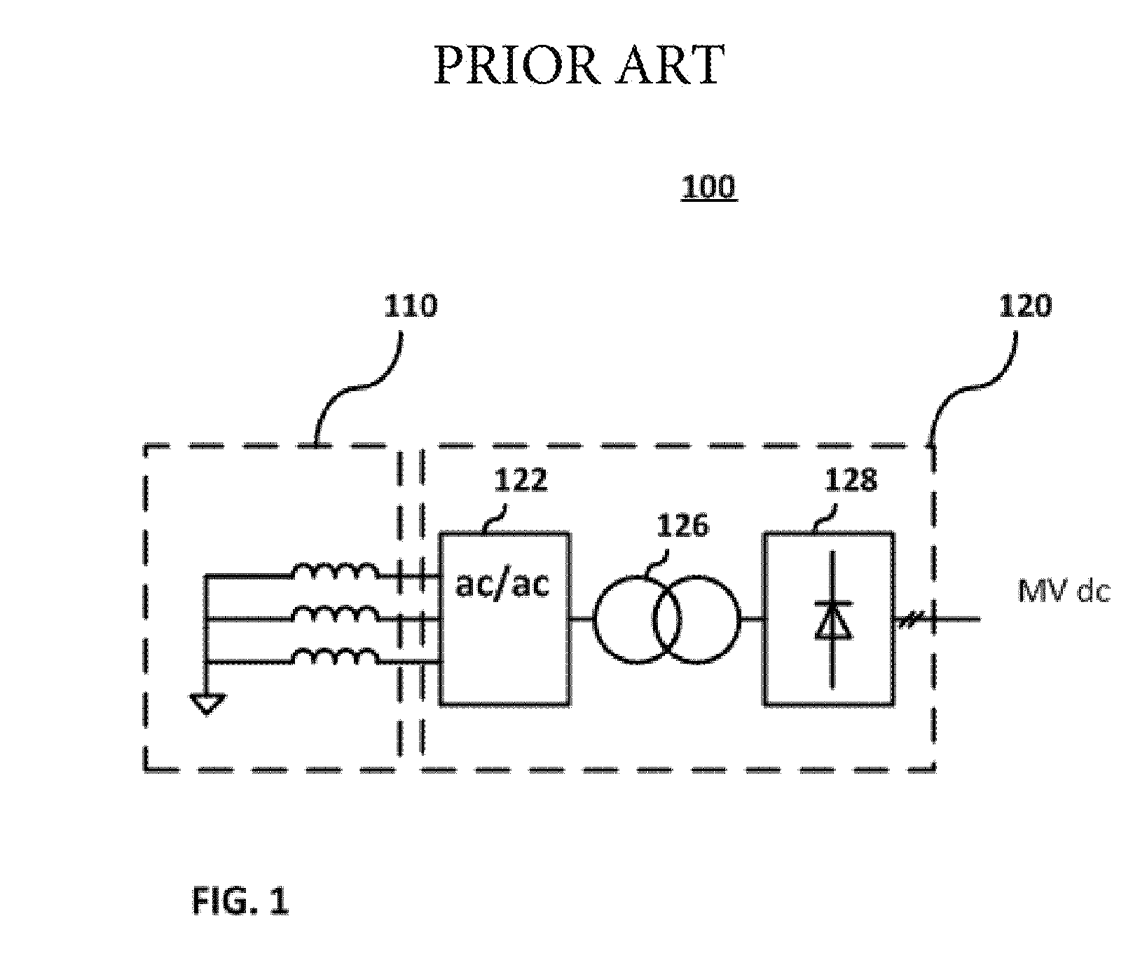
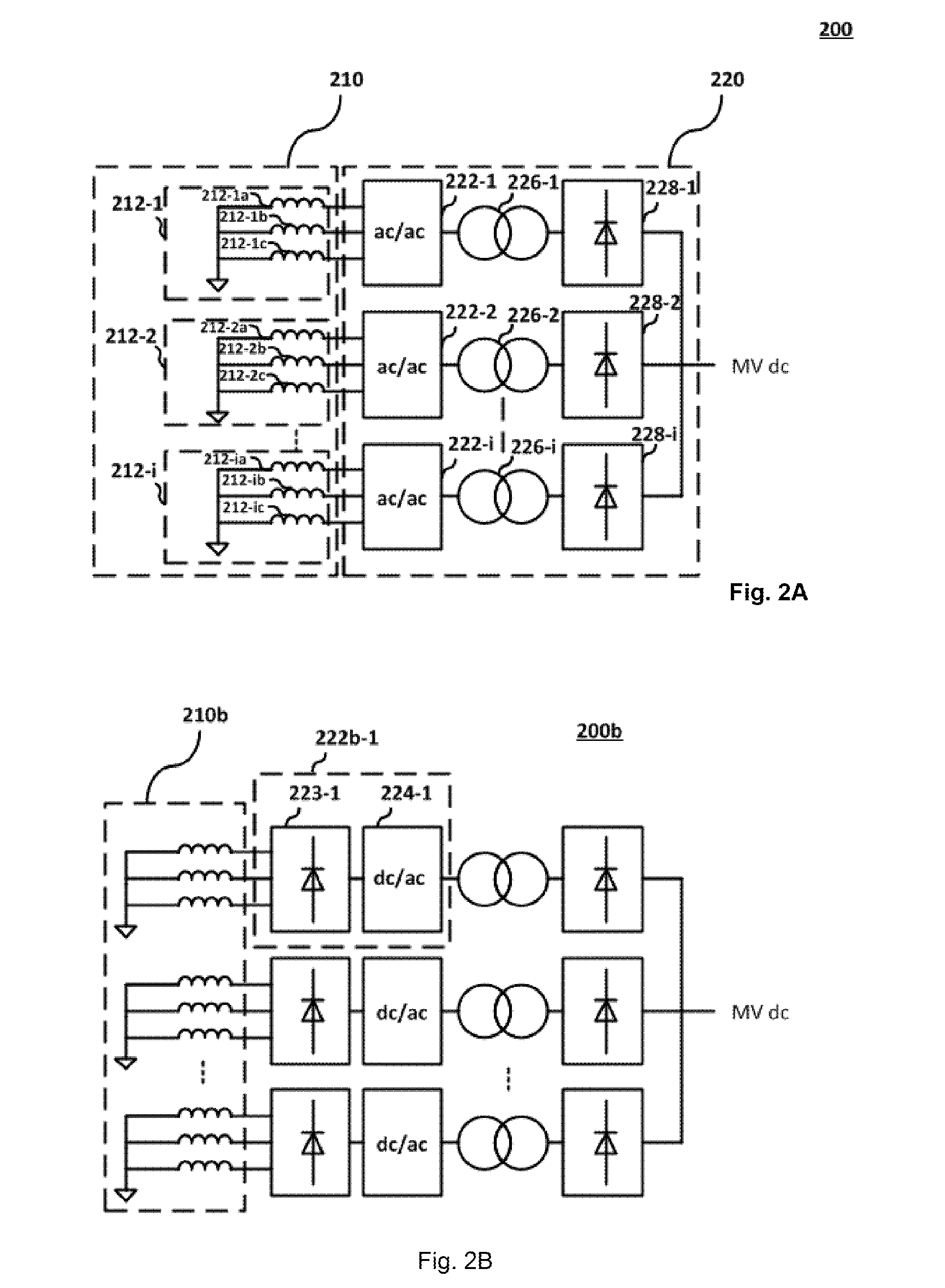
[0026]FIG. 1 shows a prior art DC generation-conversion system. Generation-conversion system 100 includes one 3-phase AC generator 110 and a conversion line 120 having an AC / AC matrix converter 122, a Low Voltage / Medium Voltage (LV / MV), Medium Frequency / High Frequency (MF / HF) transformer 126, and a diode rectifier 128. Alternatively, instead of an AC / AC matrix converter the conversion line could have a rectifier in series with a DC / AC inverter.

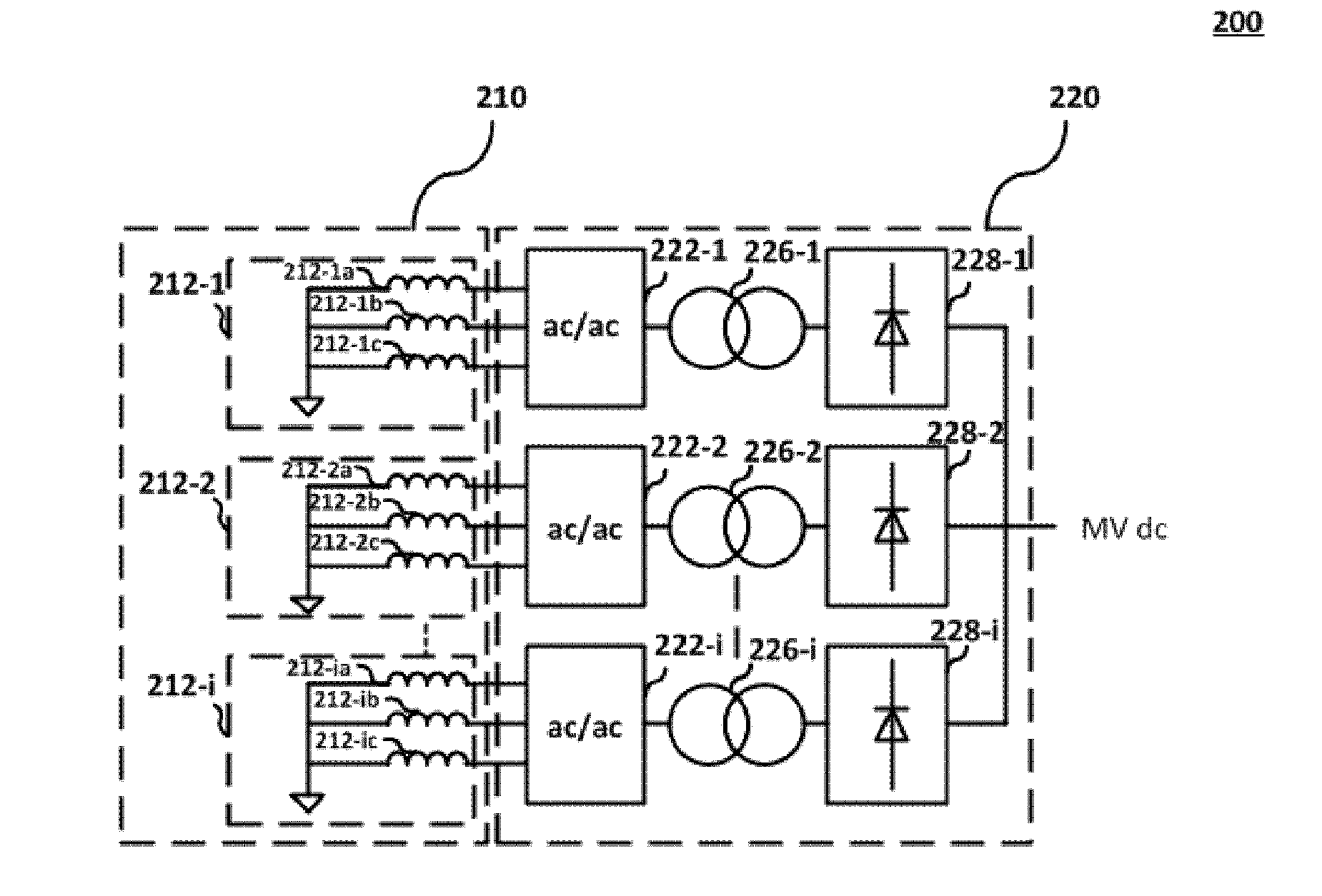
[0027]FIG. 2A shows a multiphase generation-conversion system. Generation-conversion system 200 includes a multiphase generator 210 and a conversion system 220. Multiphase generator 210 has i number of multiphase stators (212-1, 212-2 . . . 212-i). Each multiphase stator includes 3 phase legs [(212-1a , 212-1b , 212-1c ), (212-2a, 212-2b, 212-2c), (212-ia, 212-ib, 212-ic)]. Each phase leg may correspond to a winding of the multiphase stator and carry a single distinct phase of the multiphase stator. The phase legs of each stator are coupled to...


PUM


Abstract

Multiphase generator-conversion systems and clusters are disclosed. The multiphase generator-conversion systems include a multiphase n-stator generator, n conversion lines and a transformer module. Each n conversion line is coupled to the plurality of phase lines of one of the n stators, respectively. Each conversion line comprises a rectification module, coupled to the respective plurality of phase lines, configured to receive a multiphase AC voltage and generate a first DC voltage at an output. A dc / ac inverter is coupled to the output of the respective rectification module. The dc / ac inverter receives the first dc voltage and generates a single-phase AC voltage at an output. The transformer module is arranged to receive the n single-phases of the dc / ac inverters and generate an n-phase AC voltage at an output. This voltage is input to a single diode rectifier. Multiphase generator-conversion clusters include multiphase generator-conversion systems arranged to be coupled to a diode rectifier.

Description

BACKGROUND[0001]The present disclosure relates to energy generation and more specifically to multiphase generator-conversion systems.[0002]Modern wind turbines are commonly used to supply electricity into the electrical grid. Although the electrical grid is typically an AC grid, some applications exist for which DC technologies may be used. That may be the case of offshore wind power plants, where DC wind turbine power plants may be used instead of AC wind turbine power plants if they have to be connected to a high-voltage, direct current (HVDC) link. DC wind turbine power plants are wind turbine power plants with an internal DC collection grid, instead of a conventional AC collection grid.[0003]Typically, some wind turbines employ permanent magnet generators. One type of permanent magnet generators are multiphase AC generators with n i-phase stators (typically 3-phase stators). In order to implement DC wind power plants using conventional multiphase AC wind turbine generators, the ...

Claims


Application Information

Patent Timeline
Patent Type & Authority Applications(United States)
IPC IPC(8): H02J3/38H02M5/04H02M5/42H02M7/06
CPCH02J3/386H02M5/42H02M5/04H02M7/06H02M5/22H02M5/458H02M7/04H02J2300/28H02J3/381Y02E10/76
Inventor GOMIS, ORIOL BELLMUNTGARCIA, LOSE LUIS DOMINGUEZARAGUES, MONICA PENALBA
Owner GE RENEWABLE TECH WIND BV
Learn More