Inverter control method

a technology of inverter control and control method, which is applied in the direction of ac-dc conversion, power conversion systems, electrical equipment, etc., can solve the problems of power switch thermal management, power loss, and junction temperature increase, so as to improve reliability and availability, reduce thermal stress of power switch in power electronic system, and uniformly distribute

Inactive Publication Date: 2016-10-27
ROLLS ROYCE PLC
View PDF1 Cites 20 Cited by
  • Summary
  • Abstract
  • Description
  • Claims
  • Application Information

AI Technical Summary

Benefits of technology

[0014]Accordingly, a control technique is provided that can improve the reliability and availability of, for example, power switches in a power electronics system without any modification of the hardware design. The therm...

Problems solved by technology

However, thermal management of power switches has been a challenge, especially in high ambient operating, temperature environment.
Due to the non-ideal characteristics of power switches (for example internal resistance and parasitic capacitances and inductances for example), power losses are seen (typically, referred to as conduction and switching losses) during operation of the power switches.
Losses in a power switch cause the junction temperature to increase.
As the power switch is heated above its rated operating junction temperature, its reliability will typically be affected as every 10 degree Celsius increment above rated temperature will reduce the lifetime of the power switch by half.
Hardware-based solutions are generally based on the addition of resonant tanks into the system to enable zero voltage or zero current switching of power switches, leading to reduced switching losses.
However, th...

Method used


Image

  • Inverter control method
  • Inverter control method
  • Inverter control method

Examples


Embodiment Construction

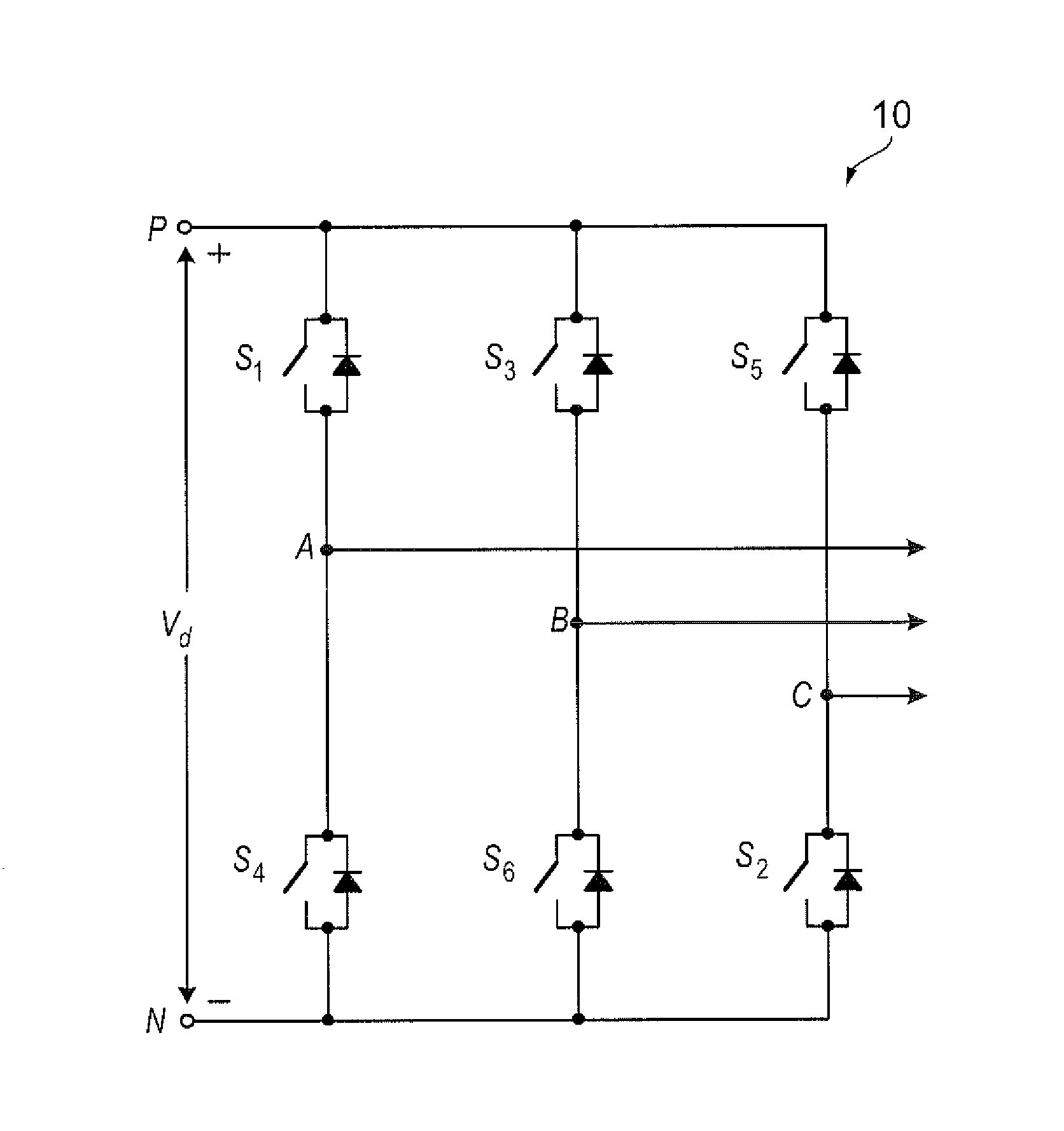
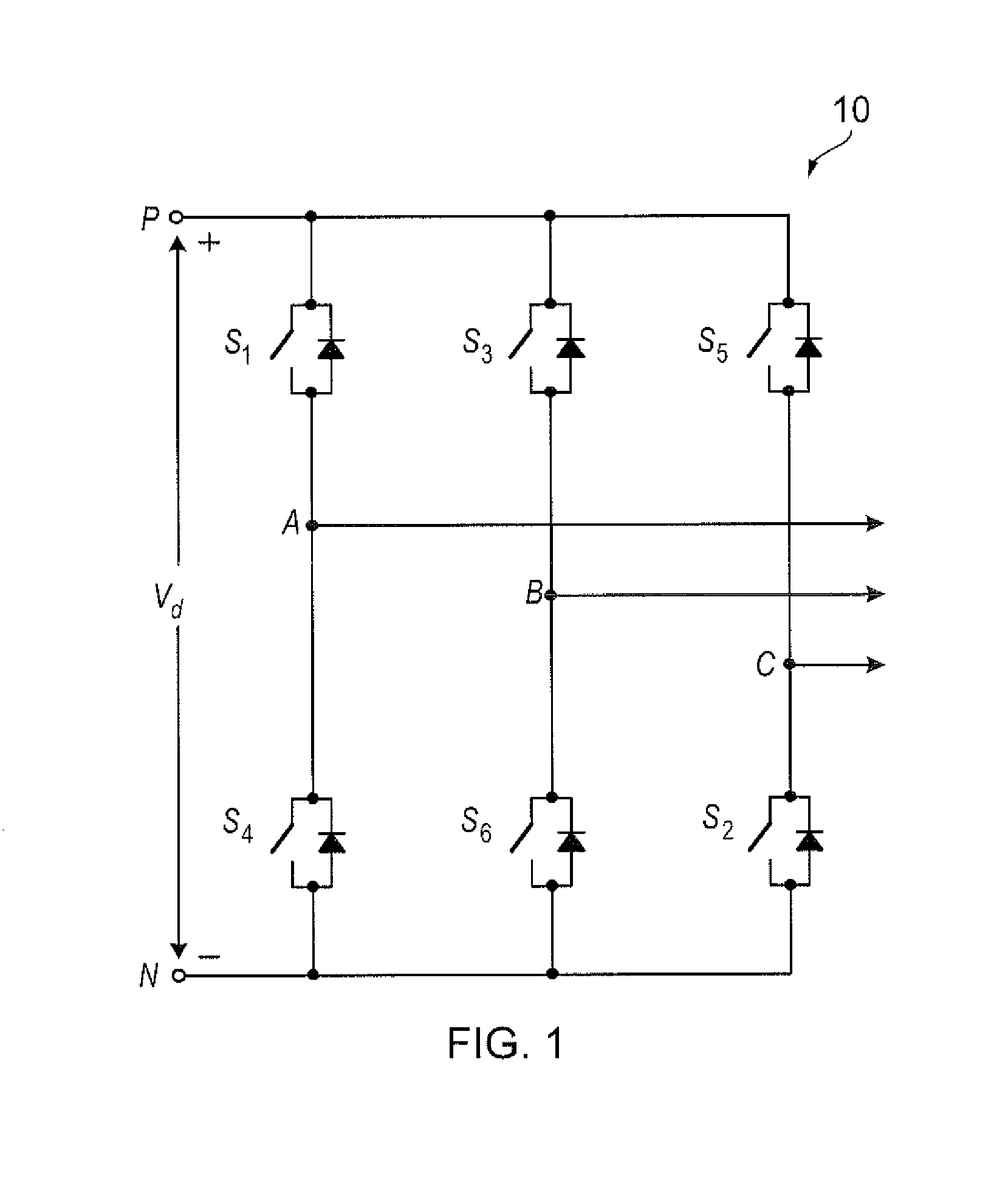
[0038]The present disclosure is applicable to three-phase power converter systems that use pulse-width modulation strategy to control the switching of power switches, for example. An example of a (generalised) suitable three-phase power converter system is shown in FIG. 1. The three-phase converter 10, also referred to as an inverter, shown in FIG. 1 is used to explain the concept of this disclosure.

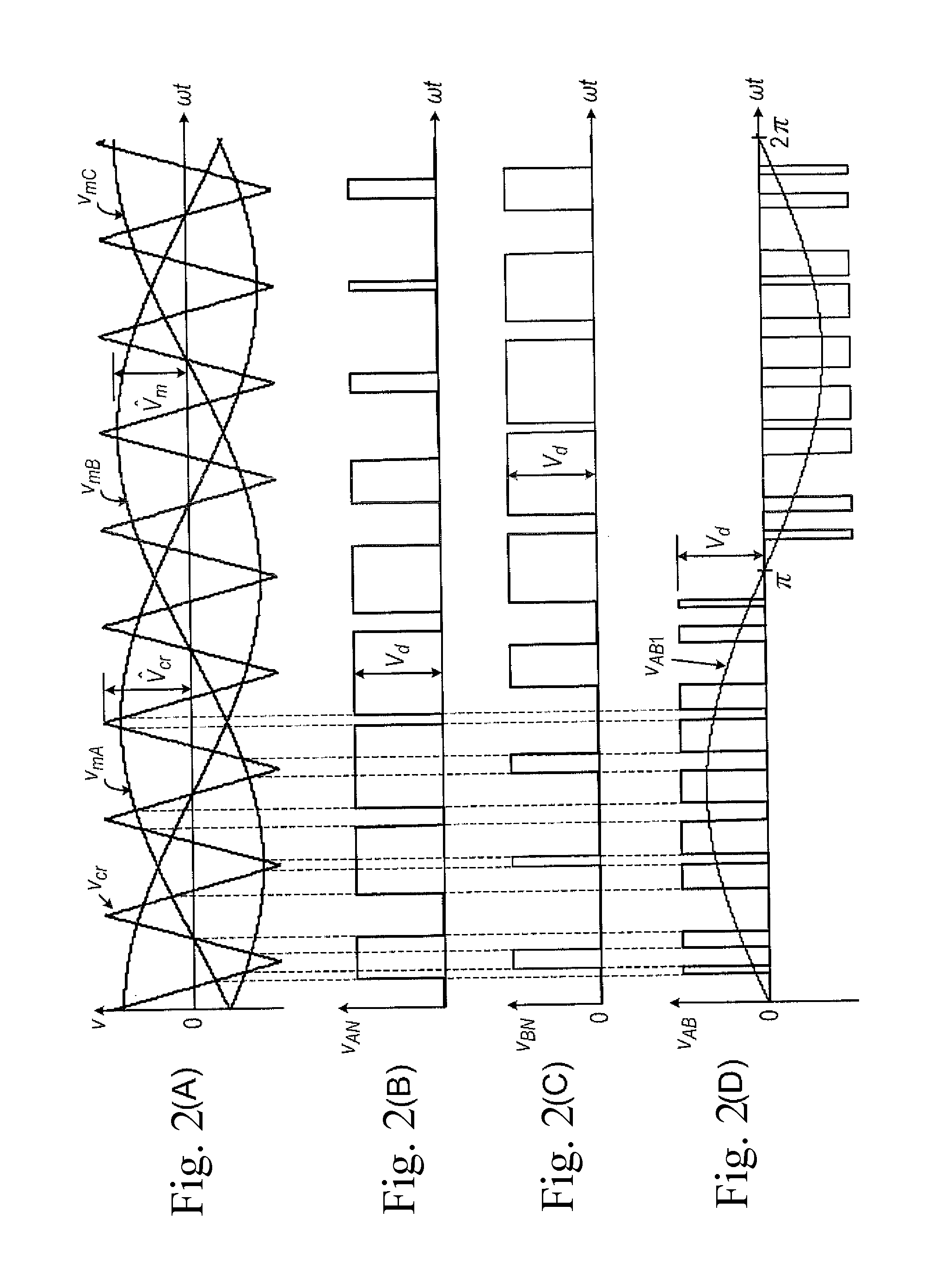
[0039]In general, to generate AC output waveforms from the DC supply Vd in FIG. 1, power switches S1-S6 of the inverter are turned on and off according to a sequence specified by a modulation strategy, For example, a sinusoidal pulse-width modulation strategy can be applied, which is a strategy known to the skilled person. An example is shown in the uppermost plot shown in FIG. 2, where VmA, VmB, VmC are the three-phase sinusoidal modulating waves and Vcr is a triangular carrier wave. The gating signals for a conventional two-level inverter, e.g. as shown in FIG. 1, operated using PWM ca...


PUM


Abstract

A method of controlling an inverter, in which the inverter includes a single-phase inverter arrangement comprising a complementary pair of power switches, comprises the steps of:
controlling the complementary pair of power switches with a modulating signal to output an AC signal;
judging which of the power switches in the complementary pair of power switches is at a higher temperature;
determining the magnitude and sign of a DC offset signal to apply to the modulating signal to reduce the total current in the power switch judged to be at the higher temperature; and
applying the DC offset signal to the modulating signal.

Description

[0001]This disclosure claims the benefit of UK Patent Application No. GB 1506183.1, filed on 23 Apr. 2015, which is hereby incorporated herein in its entirety.FIELD OF THE DISCLOSURE[0002]The present disclosure principally, but not exclusively, relates to a method for uniform distribution of thermal stress amongst devices in a power converter, such as a DC to AC converter.BACKGROUND OF THE DISCLOSURE[0003]Power electronics is a technology that facilitates electrical energy conversion between source and load based on the combined functionality of energy systems, electronics and control. The use of power electronics has been widely seen in various applications, such as aerospace, military, automotive, computing etc., for proper and energy efficient operation.[0004]In power electronics systems, the conversion process begins when the controller, which is a low-power digital or analog electronic circuit, operates the power converter / switches according to a modulation strategy.[0005]Power...

Claims


Application Information

Patent Timeline
IPC IPC(8): H02M7/537
CPCH02M7/537H02M1/32H02M7/5387H02M7/5395H02M1/327H02M7/4833
Inventor LEE, MENG YEONGGAJANAYAKE, CHANDANA JAYAMAPATHIJAYASINGHE, SHANTHA DHARMASIRI GAMININADARAJAN, SIVAKUMARGUPTA, AMIT KUMAR
Owner ROLLS ROYCE PLC
Why Eureka
Try Eureka