
Electric cable for use in a welding device

a technology of welding device and electric cable, which is applied in the direction of coupling device connection, plastic/resin/waxes insulator, organic insulator, etc., can solve the problems that conventional electric cables with control lights cannot withstand these conditions, and the control possibility has not existed, so as to achieve good light transmission, high resistance of electric cable, and sufficient flame resistance of plug connector

Active Publication Date: 2016-11-03
BALLUFF
View PDF11 Cites 2 Cited by
  • Summary
  • Abstract
  • Description
  • Claims
  • Application Information

AI Technical Summary

Benefits of technology

The invention is a plug connector with a light source that is protected from the conditions of a welding insert. The material of the plug connector is highly resistant to welding insert conditions, making it ideal for use as a control line for a welding device. The material also allows for good transmission of the light emitted by the LED light source. The use of an LED as the light source is beneficial as it has high heat tolerance and emits little heat. The wires have insulation made of materials such as silicones, perfluorocarbons, cross-linked polyolefins, mica, glass fibres, ceramic fibres, and mixtures thereof, which ensures uniform behavior in the case of thermal stress. The patent serves to protect the light source in a plug connector and provide a reliable and efficient way to control and monitor the welding process.

Problems solved by technology

However, this control possibility has not existed for electric cables for welding devices until now.
Even electric cables known today without control lights, which are used in welding devices must be replaced regularly, as an exposure of cable wires occurs very often due to the rough conditions during welding.
Conventional electric cables with control lights could not withstand these conditions even in the short term.

Method used


Image

  • Electric cable for use in a welding device
  • Electric cable for use in a welding device
  • Electric cable for use in a welding device

Examples


Embodiment Construction

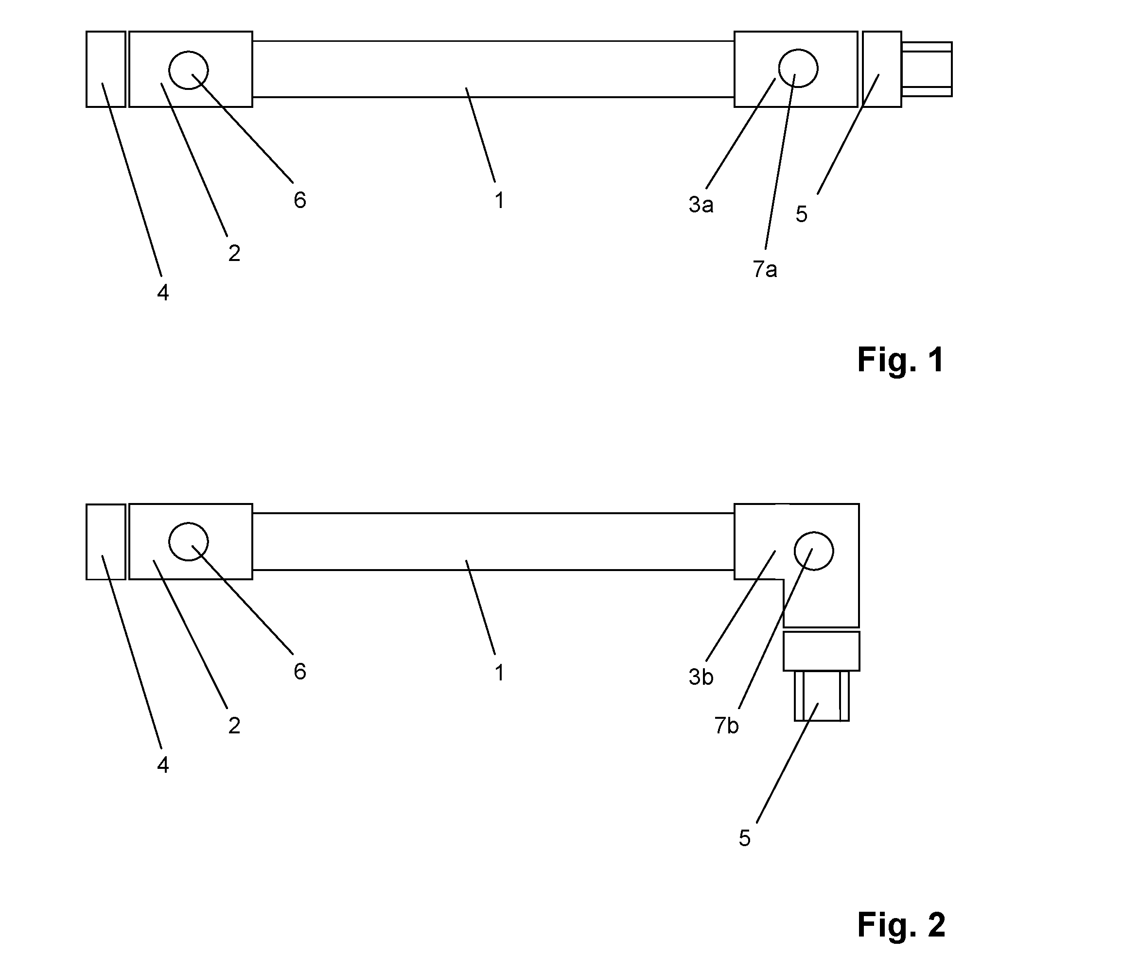
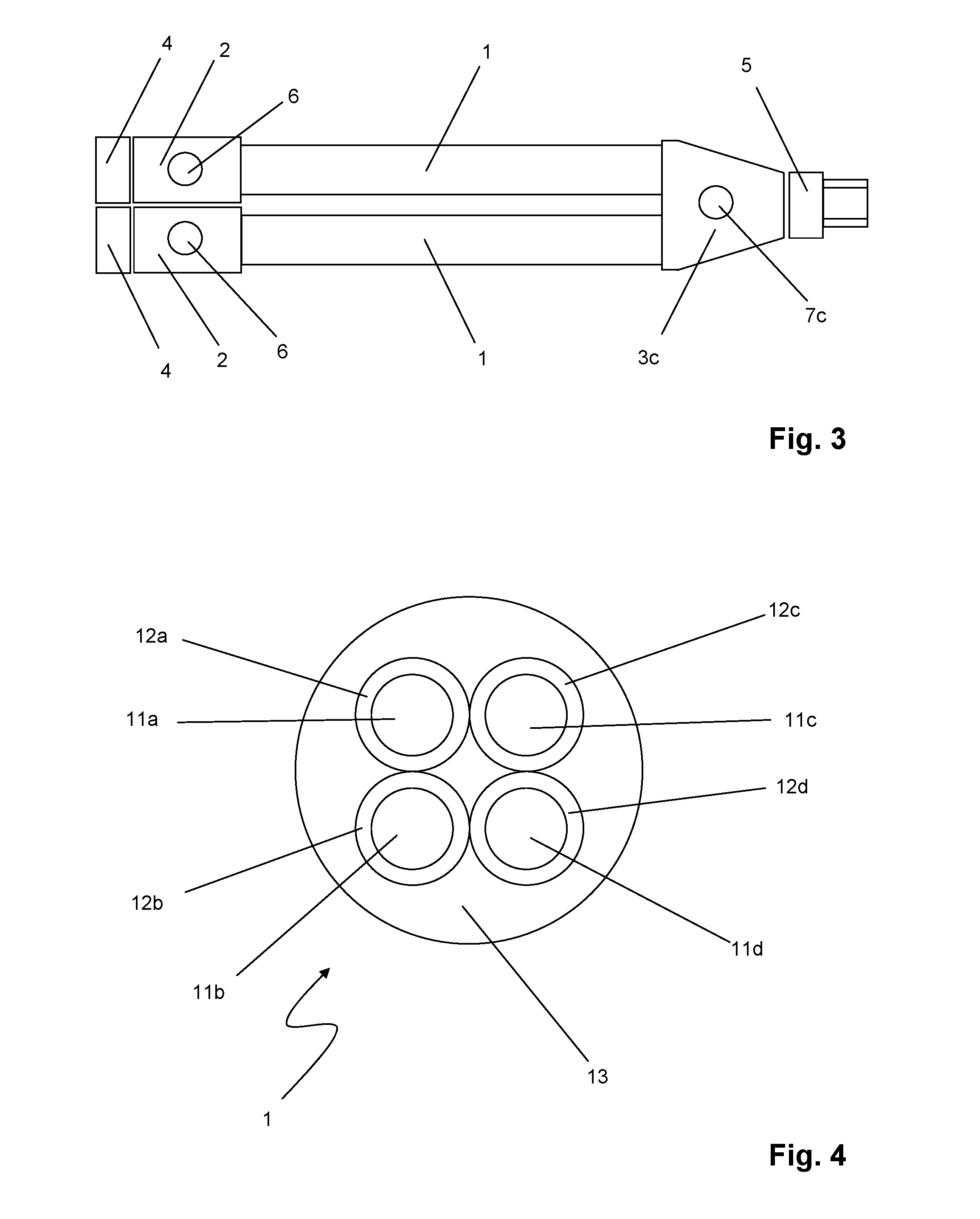
[0024]The resistance of cables to welding conditions was investigated in comparative examples (VB1 to VB7) and examples according to the invention (B1 and B2) of electric cables. The structure of such an electric cable is shown in three embodiments in FIGS. 1, 2 and 3. FIG. 4 shows a longitudinal cut through the current line 1 of this electric cable. The current line 1 comprises four wires 11a, 11b, 11c, 11d. Each wire, 11a, 11b, 11c, 11d has a wire insulation 12a, 12b, 12c, 12d. All wire insulations 12a, 12b, 12c, 12d are surrounded by a mutual coating 13. A first plug connector 2 is arranged on the first end of the current line 1. A second plug connector 3a, 3b, 3c is arranged on the second end of the current line. The second plug connector can be embodied as a linear plug connector 3a, as an angled plug connector 3b or as a Y-plug connector 3c. The plug connectors 2, 3a, 3b, 3c are each crimped onto the current line 1. A first connection nut 4 is arranged on the first plug connec...


PUM

PropertyMeasurementUnit
tensile strengthaaaaaaaaaa
elongation at breakaaaaaaaaaa
cross-sectional areaaaaaaaaaaa

Abstract

An electric cable includes at least one current line having first and second ends, including several wires, a first plug connector and at least one second plug connector arranged on the first and second ends, respectively. At least one plug connector includes a material having A) 98.0% to 99.8% by weight of a polymer selected from the group consisting of polyurethane (PU), styrene-butadiene block copolymers (SBS), perfluorocarbons and mixtures thereof, and B) 0.2% to 2.0% by weight additives. The total of components A and B results in 100% by weight. A first connection nut and at least one second connection nut are arranged on the first and second plug connectors, respectively. At least one light source is arranged in a first plug connector and / or in a second plug connector and is configured in order to be supplied with electrical energy by at least one wire of the current line.

Description

CROSS REFERENCE TO RELATED APPLICATIONS[0001]Applicant claims priority under 35 U.S.C. §119 of German Application No. 20 2015 102 166.6 filed Apr. 29, 2015, the disclosure of which is incorporated by reference.BACKGROUND OF THE INVENTION[0002]1. Field of the Invention[0003]The present invention relates to an electric cable. Furthermore, the invention relates to the use of the electric cable as a control line for a welding device, in particular in the automotive industry.[0004]2. Prior Art[0005]Welding devices, in particular welding robots for automated industrial applications, require for their control electric cables which can withstand stresses. It is required that such electric cables are flame-retardant according to different standards such as IEC 60332-2, VDE 0482-265-2-2 and EN 50265-2-2. Furthermore, they must be able to be withstand contact with welding beads, i.e. metal which melts and sprays during the welding, over a long period of time.[0006]For the functional control of...

Claims


Application Information

Patent Timeline
Patent Type & Authority Applications(United States)
IPC IPC(8): H01R13/533H01B3/46H01B7/295H01R13/717H01R9/11
CPCH01R13/533H01R13/7175H01B3/46H01B7/295H01R9/11H01B3/30
Inventor MAYER-ROSA, MICHAELBAYER, THOMASKAMMERER, ANDREAS
Owner BALLUFF
Learn More