Double shutter shroud and tunnel for mcc bus connections

a technology of mcc bus connection and double shutter shroud, which is applied in the direction of shutters/guards preventing contact access, electrical equipment, substation/switching arrangement details, etc., can solve the problem that industrial environments are typically exposed to pollution

Active Publication Date: 2016-11-03
SCHNEIDER ELECTRIC USA INC
View PDF8 Cites 6 Cited by
  • Summary
  • Abstract
  • Description
  • Claims
  • Application Information

AI Technical Summary

Benefits of technology

[0010]A flexible, insulating sheath located within the motor control center unit, surrounds and protects the stab. The flexible, insulating sheath has one end fastened to the inward-facing back wall of the motor control center unit. The flexible, insulating sheath is aligned with the aperture in the back wall of the motor control center unit where the stab passes through on its way to contact the bus. The flexible, insulating sheath forms the second portion of the protective tunnel with the first and second shrouds. The protective tunnel formed by combination of the double shutter shroud and the flexible sheath surrounding the stab, protects the stab from contamination, helps prevent a short circuit between different phase busses, and protects an operator from electrical hazard of touching the bus or stab with tools or fingers.
[0011]The shrouds are coupled and are overlapped before electrical connection is made between the stab and the bus, so that a clear path is provided for the stab to travel from a retracted or disconnected position to an advanced or connected position. The protective tunnel prevents misplaced tools or other conductive material from falling into the pathway of the stab, which could otherwise be pushed by the stab toward the bus as it travels, causing an arc flash.

Problems solved by technology

Contamination of electrical contacts may cause tracking and tracking may lead to arcing.
Industrial environments are typically exposed to pollution such as dust, salt, humidity, and atmospheric chemical agents.

Method used


Image

  • Double shutter shroud and tunnel for mcc bus connections
  • Double shutter shroud and tunnel for mcc bus connections
  • Double shutter shroud and tunnel for mcc bus connections

Examples


Embodiment Construction

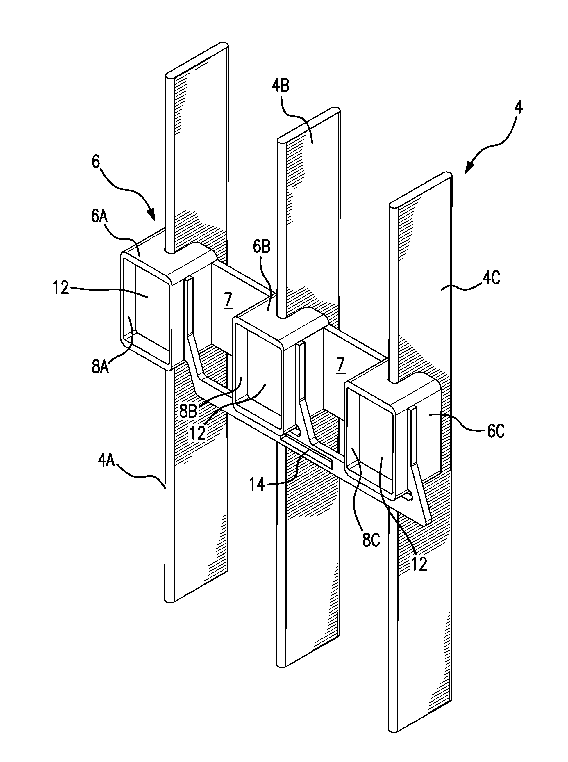
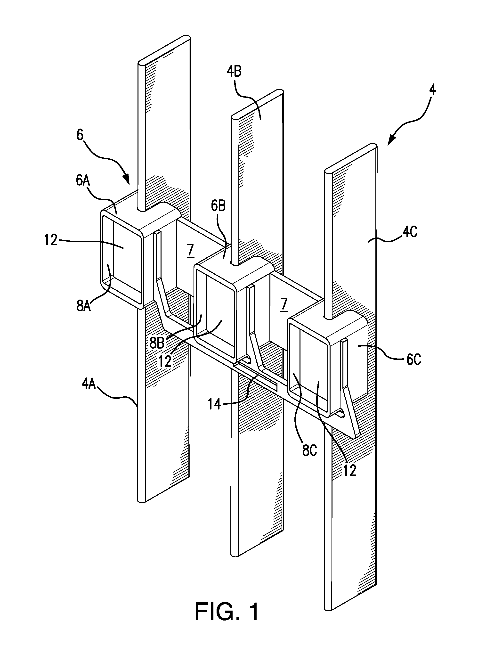
[0023]FIG. 1 is a perspective view from the top right side of a common power bus 4 running vertically along the back side of an MCC section. The power bus 4 is shown composed of three bus bars 4A, 4B, 4C, composed of copper or aluminum. The power bus 4 may be a single phase bus with two bus bars 4A and 4C carrying the single phase and one bus bar 4B being grounded. Alternately, the power bus 4 may be a three phase bus with the three bus bars 4A, 4B, 4C each carrying a different one of the three phases. There would be a significant hazard of arcing if a dielectric breakdown or short circuit were to occur between different bus bars 4A, 4B, 4C or stabs, such as by a misplaced tool touching adjacent buses or stabs. And, there would be a severe personal injury hazard to an operator by inadvertently touching a bus bar 4 or stab with tools or fingers.

[0024]Other phase and grounding arrangements, as well as bus bar numbers and lay outs, may exist and be accommodated by the present invention...


PUM


Abstract

A double shutter shroud (5) and a flexible sheath (11) surrounding a stab (10) of an MCC unit, form a protective tunnel (30) for the stab to connect to a bus 4. A first shroud (6) mounted on the bus, includes a first gate (12). A second shroud (20) mounted on the MCC unit includes a second gate (24). When the MCC unit slides into an MCC section, a unit key (16) opens the first gate. When the stab is advanced toward the bus, a stab key (28) opens the second gate, forming a protective tunnel (30) from the flexible sheath and through the first and second shrouds. The protective tunnel protects the stab and bus from contamination, helps prevent dielectric breakdowns and short circuits between different phase busses, and protects an operator from electrical hazard of touching the bus or stab with tools or fingers.

Description

FIELD OF THE INVENTION[0001]The invention is generally directed to a bus connection for a motor control center unit.BACKGROUND OF THE INVENTION[0002]A motor control center, also referred to as an MCC, is generally a cabinet-like structure that is divided into modular sections designed to accept a plurality of component motor control center units, also referred to as MCC units. An MCC “unit” is generally a drawer-like container of electrical components, such as circuit breakers, motor starters, relays, power meters, programmable logic controllers, and other control circuit components used for electrical power distribution in industrial and commercial applications. The MCC unit slides into an MCC section and plugs into a common power bus running vertically along the back side of the MCC section. The MCC unit includes a connector, also referred to as a stab assembly or stabs, arranged at the back side of the unit, to plug into the power bus. The stab assembly is movable within the MCC ...

Claims


Application Information

Patent Timeline
Patent Type & Authority Applications(United States)
IPC IPC(8): H02B1/14H02B1/36H02B1/21
CPCH02B1/14H02B1/36H02B1/21H02B11/24
Inventor BECERRA BECERRA, MANUEL ANTONIOCORDOVA URBIOLA, ARTURO JAVIERESPINOSA GUTIERREZ, VICTOR DANIEL
Owner SCHNEIDER ELECTRIC USA INC
Why Eureka
Try Eureka