Supercharge Your Innovation With Domain-Expert AI Agents!

Synchronized measurement device using local area network with ethernet messaging

a technology of synchronized measurement and local area network, applied in the direction of generating/distributing signals, wired architecture, instruments, etc., can solve the problem of inability to use ethernet channels, and achieve the effect of high control reliability

Active Publication Date: 2016-11-10
CRYSTAL INSTR CORP
View PDF23 Cites 11 Cited by
  • Summary
  • Abstract
  • Description
  • Claims
  • Application Information

AI Technical Summary

Benefits of technology

This patent describes a network of devices that can sample and collect dynamic data, like seismic or vibration data, from the same event. The devices are connected through a network and communicate with a central processing unit (CPU) using Ethernet. The devices have built-in sensors and analog-to-digital converters for converting the analog data to digital. The network also includes a master clock to synchronize the sampling clocks on each device. The device's sampling clock is derived from a local clock, and the network allows the host to send time synchronization messages to the devices and receive them back to synchronize the measurement data. The technical effect of this invention is that it enables accurate synchronization of measurement devices and real-time data transmission over a network.

Problems solved by technology

While an Ethernet channel can be used to send and receive data, program code or even commands, there are cases when an Ethernet channel is not usable such as when TCP / IP protocol has not been established.

Method used


Image

  • Synchronized measurement device using local area network with ethernet messaging
  • Synchronized measurement device using local area network with ethernet messaging
  • Synchronized measurement device using local area network with ethernet messaging

Examples


Embodiment Construction

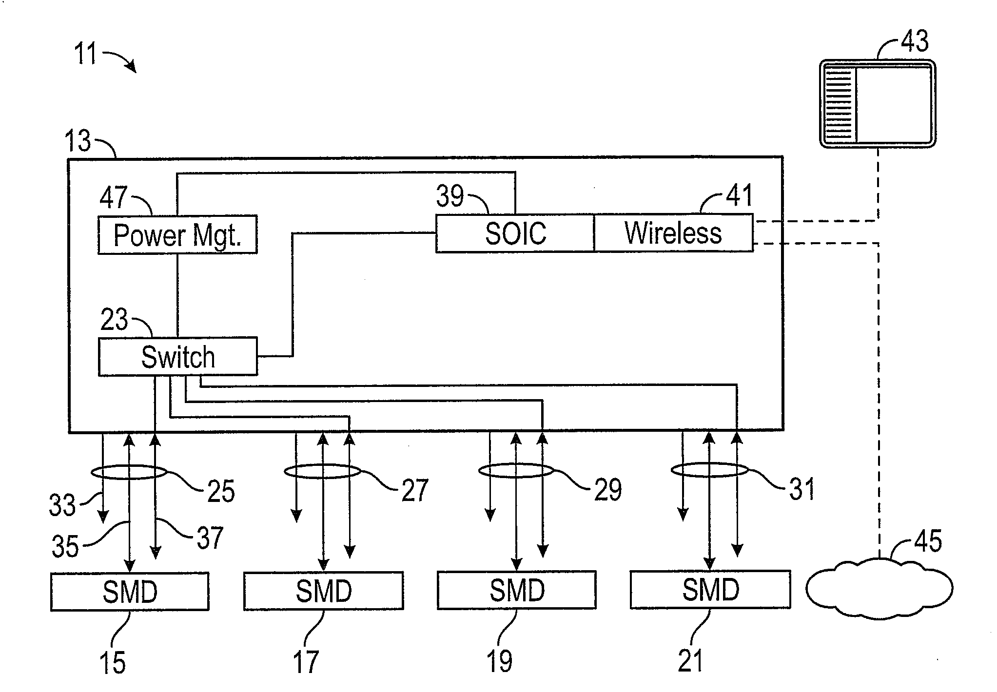
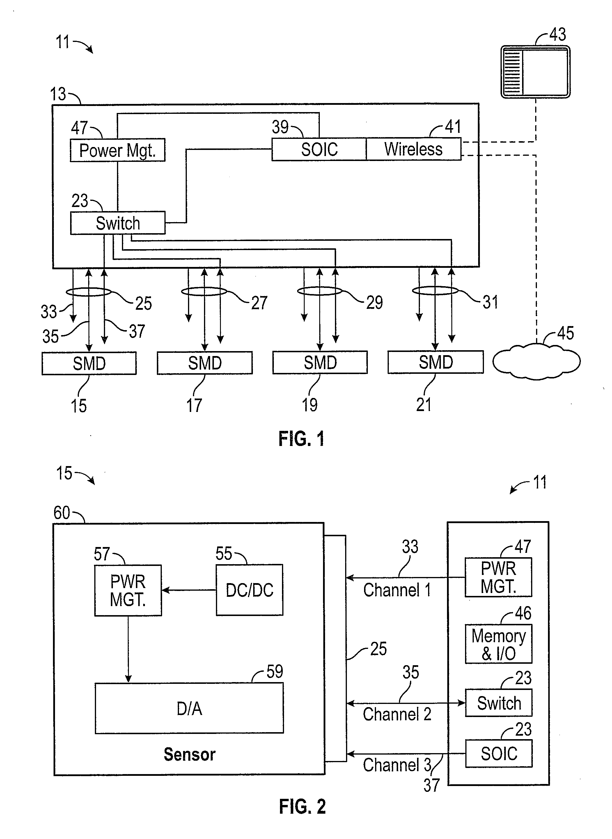
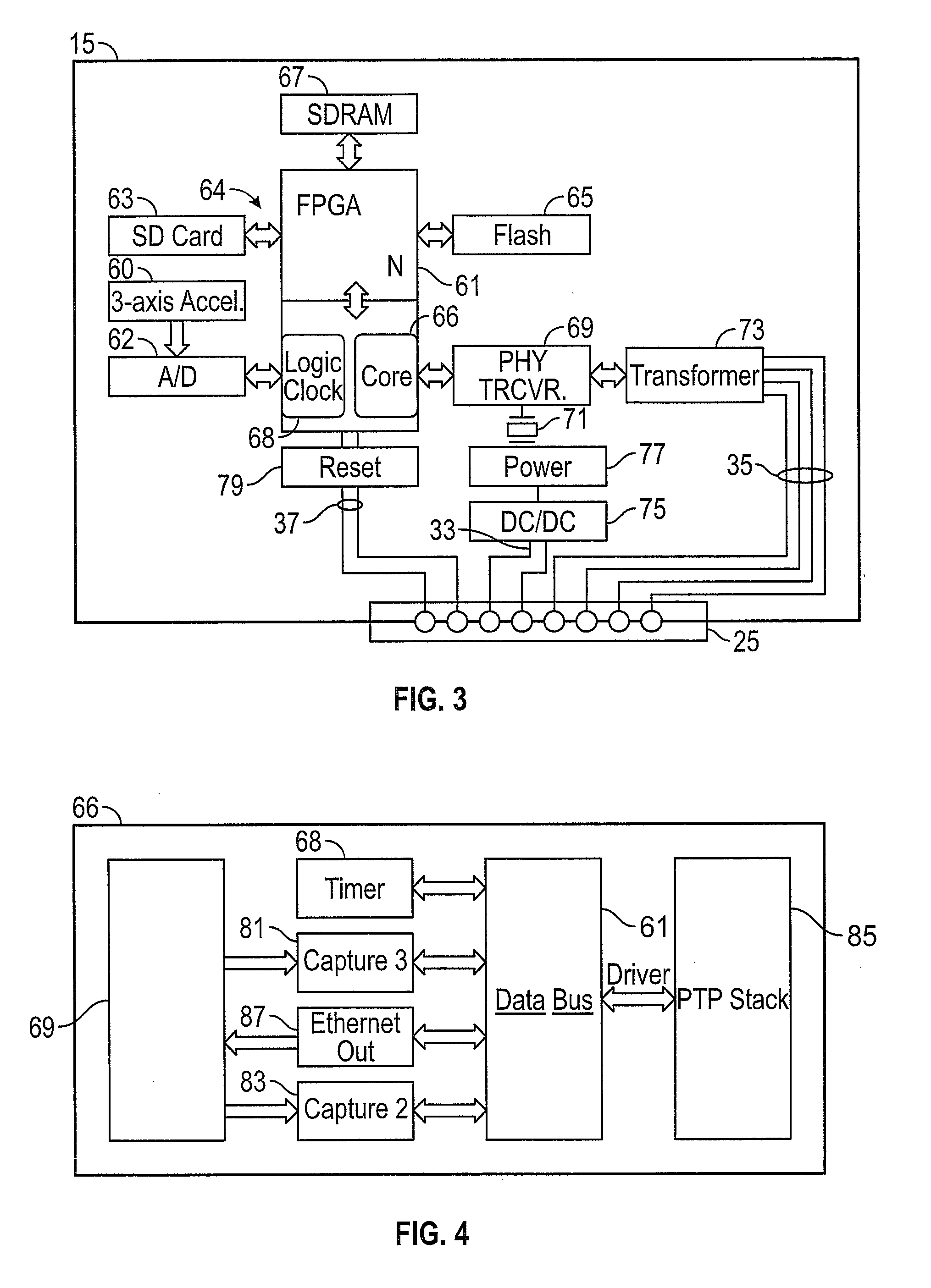
[0019]With reference to FIG. 1 an area network 11 features a host device 13 communicating with sensor measurement devices 15, 17, 19 and 21. The host device 13 has a network switch 23 with 8-wire connectors 25, 27, 29 and 31 that may be standard RJ45 connectors. Each sensor measurement device, such as device 15, communicates through an associated connector, such as connector 25 using 3 dedicated channels, including a power channel 33, an Ethernet message channel 35 and an order wire channel 37 for commands. The three channels are accommodated on 8 wires for an 8-wire connector, for example of the RJ45 type. A typical allocation of wires is further discussed below with reference to FIG. 3.

[0020]The network switch 23 is a typical Ethernet message switch chip set that distributes Ethernet messages among the connectors 25, 27, 29 and 31. The network switch is connected to a fanless computer board 39 that acts as a server. The board may be a PC104 system on a chip (SOIC) type of board wi...


PUM


Abstract

A plurality of measurement devices have analog sensors that measure the dynamic signals of physical events, sample the data into digital format with time synchronized clocks and generate time stamped Ethernet messages that are sent to a remote host. The remote host has a master clock that evaluates decoded time stamped messages from the measurement devices and sends back a message with a time correction error signal relative to the master clock. This feedback signal is used by the measurement devices to correct a local clock for data sampling and new message generation. Eight wire cable and associated connectors are used to handle three channels of traffic, with four wires dedicated to Ethernet messages as one channel, another two wires dedicated to reset and other commands as a second channel and another two wires to transmit power from the host to the measurement devices as a third channel.

Description

TECHNICAL FIELD[0001]The invention relates to data transmission and collection from distributed analog sensors for dynamic signal measurement in a network.BACKGROUND OF THE INVENTION[0002]There are many applications where an array of measurement sensors is deployed to collect dynamic physical event data, such as seismic shock, vibration, temperature, strain or humidity in industrial manufacturing and testing processes, remote machinery condition monitoring, building structure monitoring, etc. A problem that arises in data collection from such events is that the data, typically dynamic analog data at various frequencies, is collected using expensive instrumentation devices. These instruments are connected to each other via various networks with phase delays, even though taken simultaneously due to differences in network path lengths or slight local clock differences or circuit latency. The kind of measurement system that cannot measure the dynamic data with synchronized clock will ma...

Claims


Application Information

Patent Timeline
Patent Type & Authority Applications(United States)
IPC IPC(8): H04W84/18G01P15/00
CPCG01P15/00H04W84/18G01D21/00G01V1/22G06F1/12H04L67/12H04Q9/04H04Q2209/10H04Q2209/30H04Q2209/845Y04S40/18H04L67/125
Inventor ZHUGE, JAMES Q.TANG, ZHENGGE
Owner CRYSTAL INSTR CORP
Features
  • R&D
  • Intellectual Property
  • Life Sciences
  • Materials
  • Tech Scout
  • Unparalleled Data Quality
  • Higher Quality Content
  • 60% Fewer Hallucinations
Learn More