

Method for producing trifluoroethylene
a trifluoroethylene and ethylene oxide technology, applied in the field of trifluoroethylene production, can solve the problems of high conversion efficiency, poor removal efficiency, and high degree of 134a and selectivity of solid reactants, and achieve efficient and stable production. , the effect of high degree of conversion and selectivity
- Summary
- Abstract
- Description
- Claims
- Application Information
AI Technical Summary
Benefits of technology
Problems solved by technology
Method used
Image

Examples
example 1
Fluidization Example 1
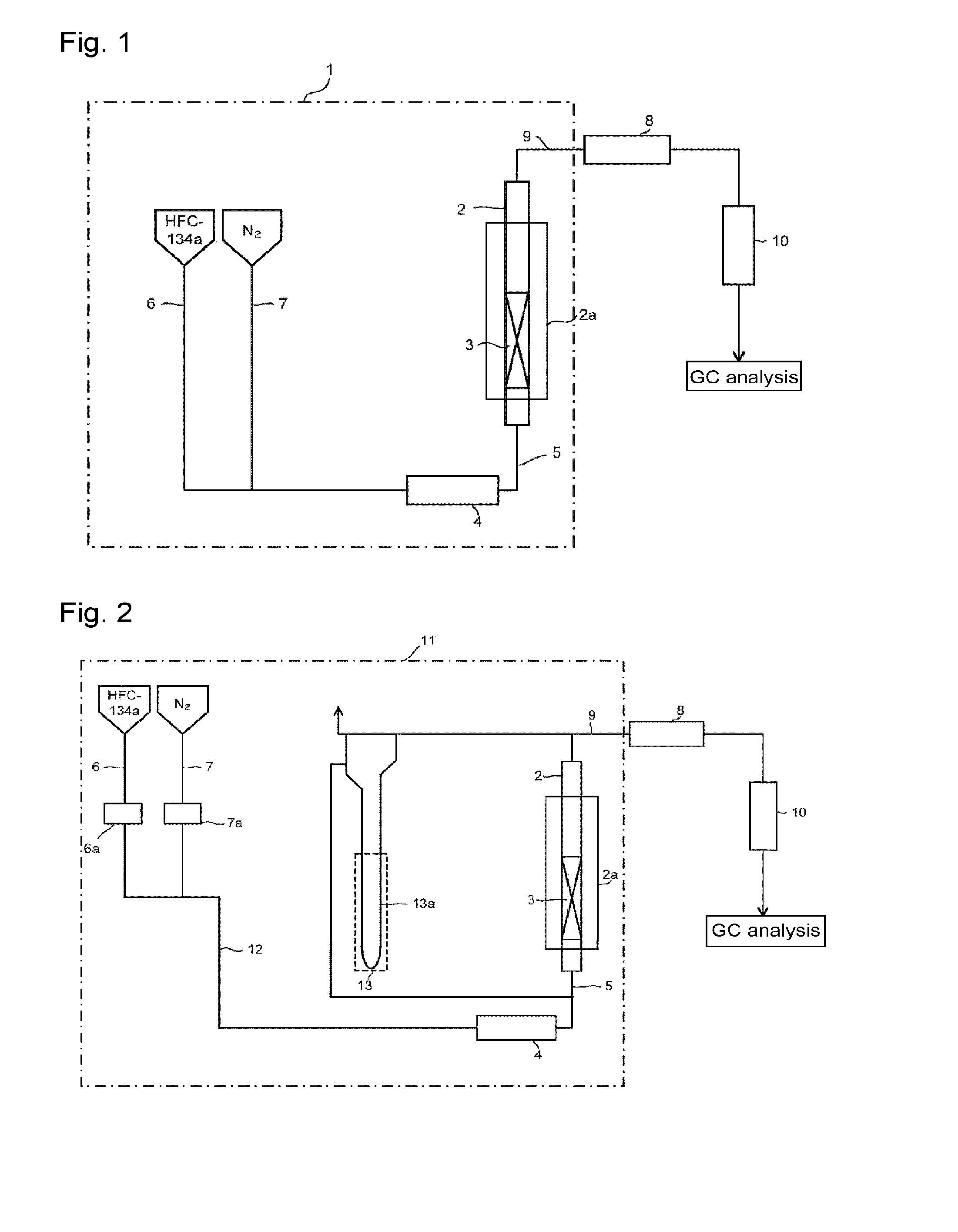
[0098]Through the fluidization visualized test apparatus packed with the solid reactant (potassium carbonate FG having an average particle size of 300 μm) shown in Reactant Packing Example 1, a nitrogen gas was made to flow at a flow rate of 151 mmol / min (linear velocity of 17 cm / s) at room temperature (25° C.) under normal pressure. On that occasion, the differential pressure between on the inlet side and on the outlet side of the visualized tester measured by the differential pressure gauge was 1,960 Pa. Further, in the visualized tester, mixing of an upper portion and a lower portion was observed in the entire layer of the solid reactant. That is, a completely fluidized state was visually confirmed.
[0099]Here, the fluidized state by visual observation of the solid reactant layer in the visualized tester was evaluated under the following standards.
[0100]◯: The upper portion and the lower portion are mixed in the entire layer of the solid reactant packed (comp...
example 2
Fluidization Example 2
[0105]Through the fluidization visualized test apparatus packed with the solid reactant (potassium carbonate FG) shown in Reactant Packing Example 1, a nitrogen gas at a flow rate of 121 mmol / min and HFC-134a at a flow rate of 30 mmol / min were mixed at room temperature (25° C.) under normal pressure and made to flow. That is, 80 mol % of a nitrogen gas and 20 mol % of HFC-134a were mixed and made to flow (linear velocity of gas mixture of 17 cm / s). On that occasion, the differential pressure between on the inlet side and on the outlet side of the visualized tester measured by the differential pressure gauge was 2,395 Pa. Further, in the visualized tester, mixing of an upper portion and a lower portion was observed in the entire layer of the solid reactant, and a completely fluidized state was visually confirmed.
[0106]Then, while the composition of HFC-134a and nitrogen (HFC-134a: N2=20:80 (by mol %)) was kept, the nitrogen gas flow rate and the HFC-134a flow ra...
example 3
Fluidization Example 3
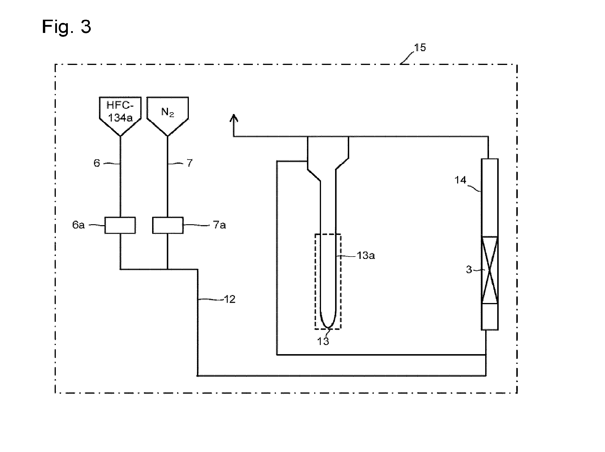
[0107]Through the fluidized bed reaction apparatus packed with the solid reactant (potassium carbonate FG) shown in Reactant Packing Example 2, a nitrogen gas was made to flow at a flow rate of 152 mmol / min (linear velocity of 17 cm / s) at room temperature (25° C.) under normal pressure. On that occasion, the differential pressure between on the inlet side and on the outlet side of the fluidized bed reactor measured by the differential pressure gauge was 2,631 Pa.
[0108]Then, the nitrogen gas flow rate was gradually decreased, and at each flow rate, the differential pressure between on the inlet side and on the outlet side of the fluidized bed reactor was measured by the differential pressure gauge. The flow rate of the nitrogen gas, the linear velocity and the differential pressure are shown in Table 3. Further, a graph obtained by plotting the differential pressure relative to the linear velocity of the nitrogen gas is shown in FIG. 6. It can be judged from Tab...
PUM
| Property | Measurement | Unit |
|---|---|---|
| particle size | aaaaa | aaaaa |
| particle size | aaaaa | aaaaa |
| linear velocity | aaaaa | aaaaa |
Abstract
Description
Claims
Application Information