Method for producing trifluoroethylene

a trifluoroethylene and ethylene glycol technology, applied in the field of trifluoroethylene production, can solve the problems of low degree of hfc-134a conversion, large amount of water formed, and heavy load of moisture removal process, and achieve high degree of 134a conversion and selectivity, and efficient production

Active Publication Date: 2016-11-17
ASAHI GLASS CO LTD
View PDF1 Cites 3 Cited by
  • Summary
  • Abstract
  • Description
  • Claims
  • Application Information

AI Technical Summary

Benefits of technology

[0015]According to the present invention, in production of HFO-1123 from HFC-134a which is an inexpensive material, HFO-1123 can be efficiently produced with sufficiently high degree of conversion of 134a and selectivity for HFO-1123, without causing problems such as clogging of the reactor, an increase in the load to the moisture removal process by formation of moisture as a by-product, and a decrease in the yield of HFO-1123.
[0016]Further, according to the production method of the present invention, by the after-described reaction, HFC-134a can be reacted with a sufficiently high degree of conversion and HFO-1123 can be obtained with a high selectivity.
[0017]Further, the production method of the present invention, in which HFC-134a and calcium oxide are reacted, has the following advantage as compared with a conventional method of reacting HFC-134a with calcium hydroxide.
[0018]That is, calcium oxide has lower adhesion property between particles as compared with calcium hydroxide, and the particles are less likely to be solidified, whereby the reactor is less likely to be clogged, and the reactor can be continuously operated stably over a long period of time. Further, risks of accidents such as a sudden pressure increase by clogging of the reactor are reduced. Further, since calcium hydroxide is produced from calcium oxide as a material, calcium oxide is available at a lower cost than calcium hydroxide. Still further, in the above reaction using calcium oxide, the amount of water formed as a by-product can be reduced as compared with a case of using calcium hydroxide, and accordingly the load of the moisture removal process required before the obtained HFO-1123 is used as a refrigerant can be reduced, formation of a carboxylic acid fluoride and a carboxylate in side reaction of HFO-1123 and water can be suppressed, and the yield of HFO-1123 can be increased.

Problems solved by technology

However, by the method disclosed in Patent Document 1, the degree of conversion of HFC-134a is low.
(1) Calcium hydroxide has a high adhesion property between particles, and the particles are likely to be solidified to clog a part of the reactor.
(2) In the reaction of calcium hydroxide with HFC-134a, the amount of water formed as a by-product tends to be large, and accordingly a load of moisture removal process tends to be heavy before the obtained HFO-1123 is used as a refrigerant.
(3) When calcium hydroxide is used for the reaction with HFC-134a, side reaction of HFO-1123 with a large amount of water formed as a by-product tends to occur and a carboxylic acid fluoride and a carboxylate are generated, thus decreasing the yield of HFO-1123.

Method used


Image

  • Method for producing trifluoroethylene
  • Method for producing trifluoroethylene
  • Method for producing trifluoroethylene

Examples


examples 2 to 5

[0072]Examples 2 to 5 were sequentially carried out without exchanging calcium oxide in the fixed bed reactor, after completion of the reaction in Example 1 until completion of Example 5. In Examples 2 to 5, HFC-134a was reacted with calcium oxide in the same manner as in Example 1 except that the reaction conditions were changed as identified in Table 1. The composition of the outlet gas collected was analyzed by gas chromatography. The analysis results are shown in Table 1.

example 1

Fluidization Example 1

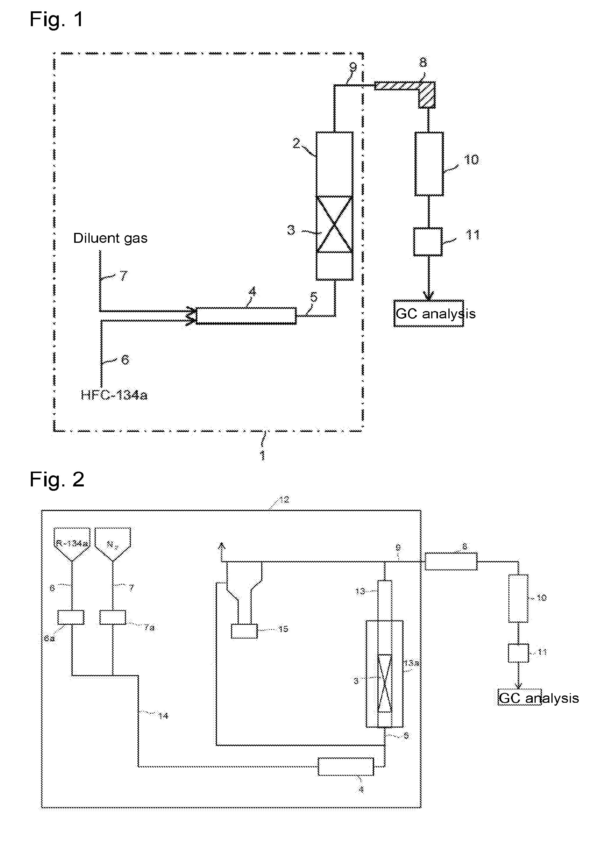
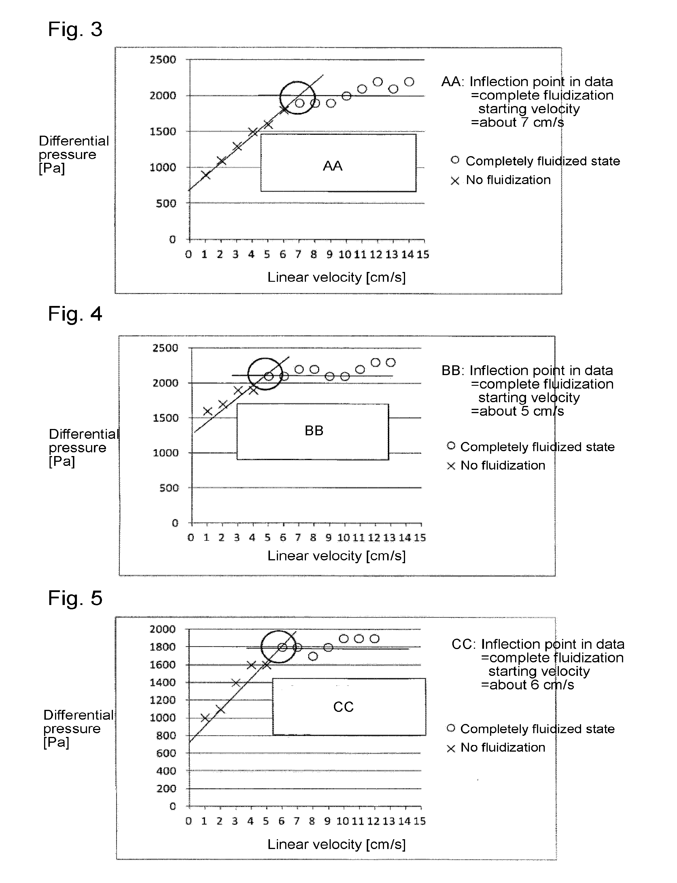
[0095]Through the fluidized bed reaction apparatus packed with the solid reactant (calcium oxide having an average particle size of 100 μm) to a height of 200 mm shown in Reactant Packing Example 3, a nitrogen gas was made to flow at a flow rate of 3.05 mol / min (linear velocity of 14 cm / s) at room temperature (25° C.) under normal pressure. On that occasion, the differential pressure between on the inlet side and on the outlet side of the fluidized bed reactor measured by the differential pressure gauge was 10,900 Pa.

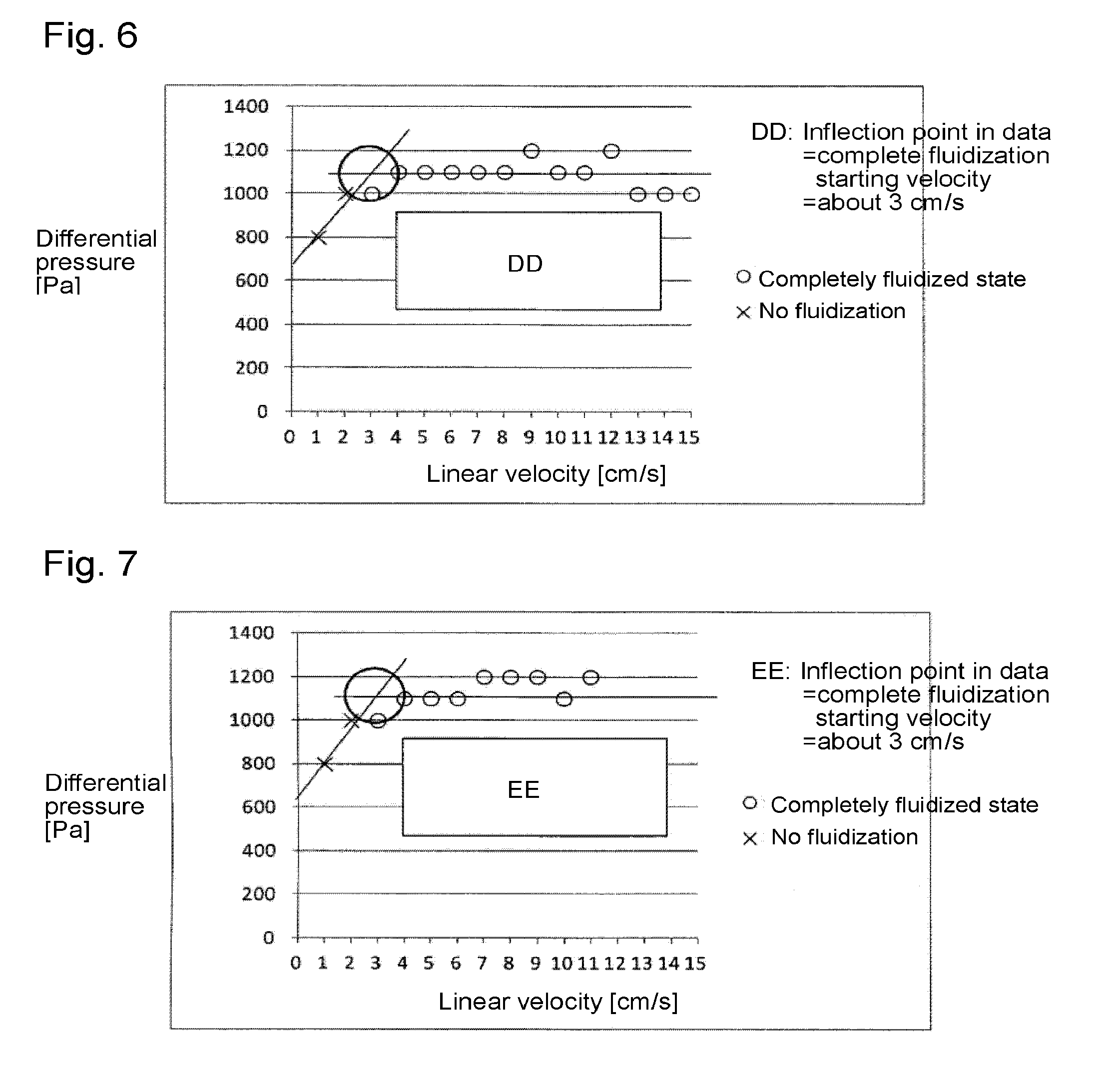
[0096]Then, the nitrogen gas flow rate was gradually decreased, and the differential pressure between on the inlet side and on the outlet side of the fluidized bed reactor was measured by the differential pressure gauge at each flow rate. The flow rate of the nitrogen gas, the linear velocity, the measured differential pressure after packing, and the calculated differential pressure obtained by calculating the difference with the Blank Differential...

example 2

Fluidization Example 2

[0097]Through the fluidized bed reaction apparatus packed with the solid reactant (calcium oxide having an average particle size of 100 μm) to a height of 300 mm shown in Reactant Packing Example 4, a nitrogen gas was made to flow at a flow rate of 2.83 mol / min (linear velocity of 13 cm / s) at room temperature (25° C.) under normal pressure. On that occasion, the differential pressure between on the inlet side and on the outlet side of the fluidized bed reactor measured by the differential pressure gauge was 10,200 Pa.

[0098]Then, the nitrogen gas flow rate was gradually decreased, and the differential pressure between on the inlet side and on the outlet side of the fluidized bed reactor was measured by the differential pressure gauge at each flow rate. The flow rate of the nitrogen gas, the linear velocity, the measured differential pressure after packing, and the calculated differential pressure obtained by calculating the difference with the Blank Differential...


PUM

PropertyMeasurementUnit
temperatureaaaaaaaaaa
pressureaaaaaaaaaa

Abstract

To efficiently produce trifluoroethylene stably by using 1,1,1,2-tetrafluoroethane, without clogging of a reactor, addition of extra process, a decrease in the yield of a product, and the like.
A material gas containing 1,1,1,2-tetrafluoroethane and calcium oxide are brought into contact with each other in a reactor. The material gas in a gaseous phase and calcium oxide in a solid phase are brought into contact with each other.

Description

TECHNICAL FIELD[0001]The present invention relates to a method for producing trifluoroethylene, more particularly, a method for producing trifluoroethylene from 1,1,1,2-tetrafluoroethane as a material.BACKGROUND ART[0002]Trifluoroethylene (HFO-1123), which has a low global warming potential (GWP), is greatly expected in recent years as a new refrigerant which may replace difluoromethane (HFC-32) and 1,1,1,2,2-pentafluoroethane (HFC-125) which are greenhouse gases.[0003]In this specification, abbreviated names (e.g. refrigerant numbers) of halogenated hydrocarbon compounds are described in brackets after the compound names. As the case requires, the abbreviated names are employed instead of the compound names.[0004]Heretofore, a method for producing such HFO-1123 from 1,1,1,2-tetrafluoroethane (HFC-134a) which is a relatively inexpensive material has been known. For example, Patent Document 1 discloses a method of subjecting HFC-134a to dehydrofluorination using a metal fluoride as a...

Claims


Application Information

Patent Timeline
Patent Type & Authority Applications(United States)
IPC IPC(8): C07C17/25B01J8/24C09K5/04
CPCC07C17/25C09K2205/126B01J8/24C09K5/045C07C21/18
Inventor NAKAMURA, MASAHIKOOKAMOTO, HIDEKAZU
Owner ASAHI GLASS CO LTD
Why Eureka
Try Eureka