
Bearing part

Active Publication Date: 2016-11-17
NIPPON STEEL CORP
View PDF0 Cites 3 Cited by
  • Summary
  • Abstract
  • Description
  • Claims
  • Application Information

AI Technical Summary

Benefits of technology

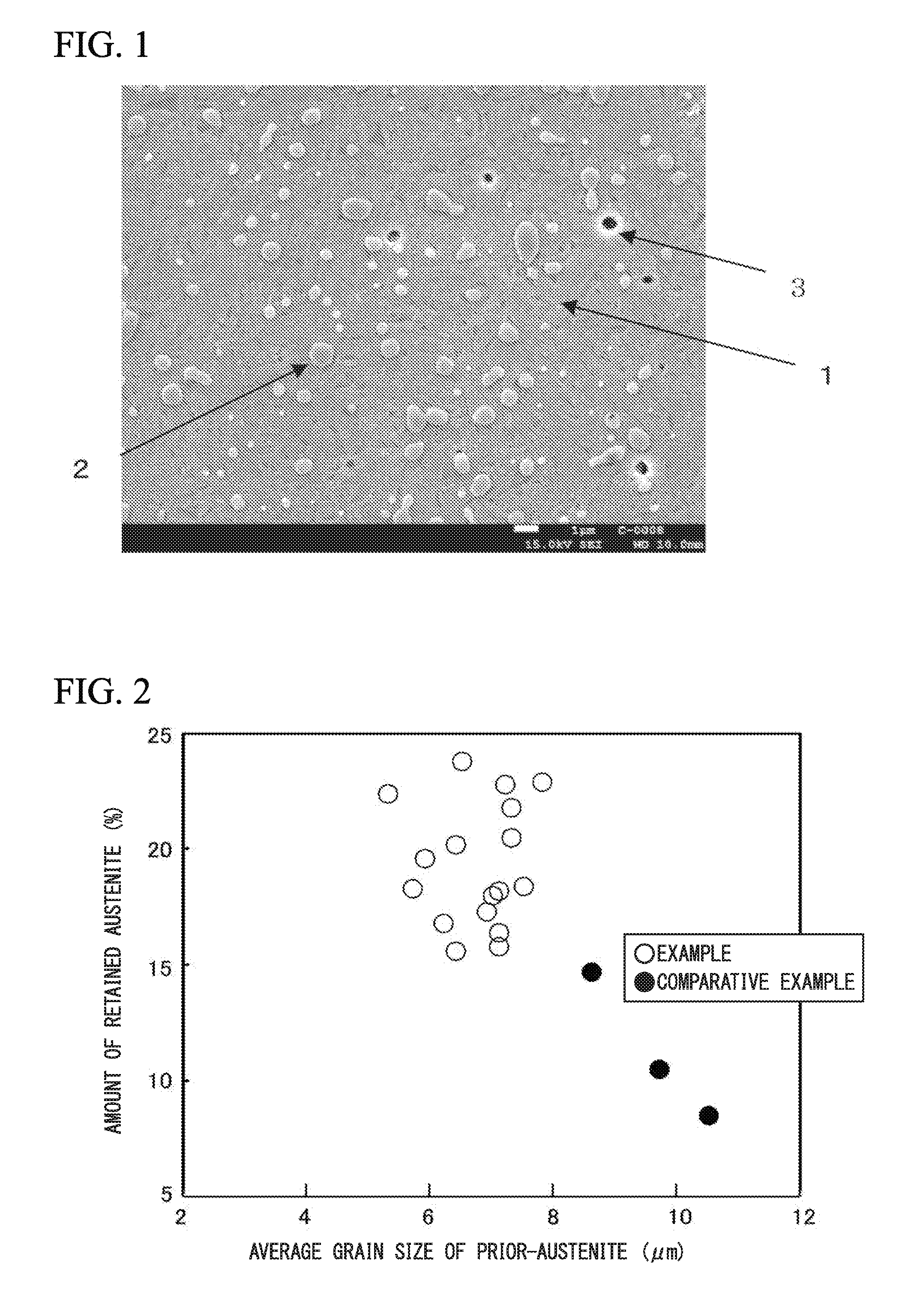
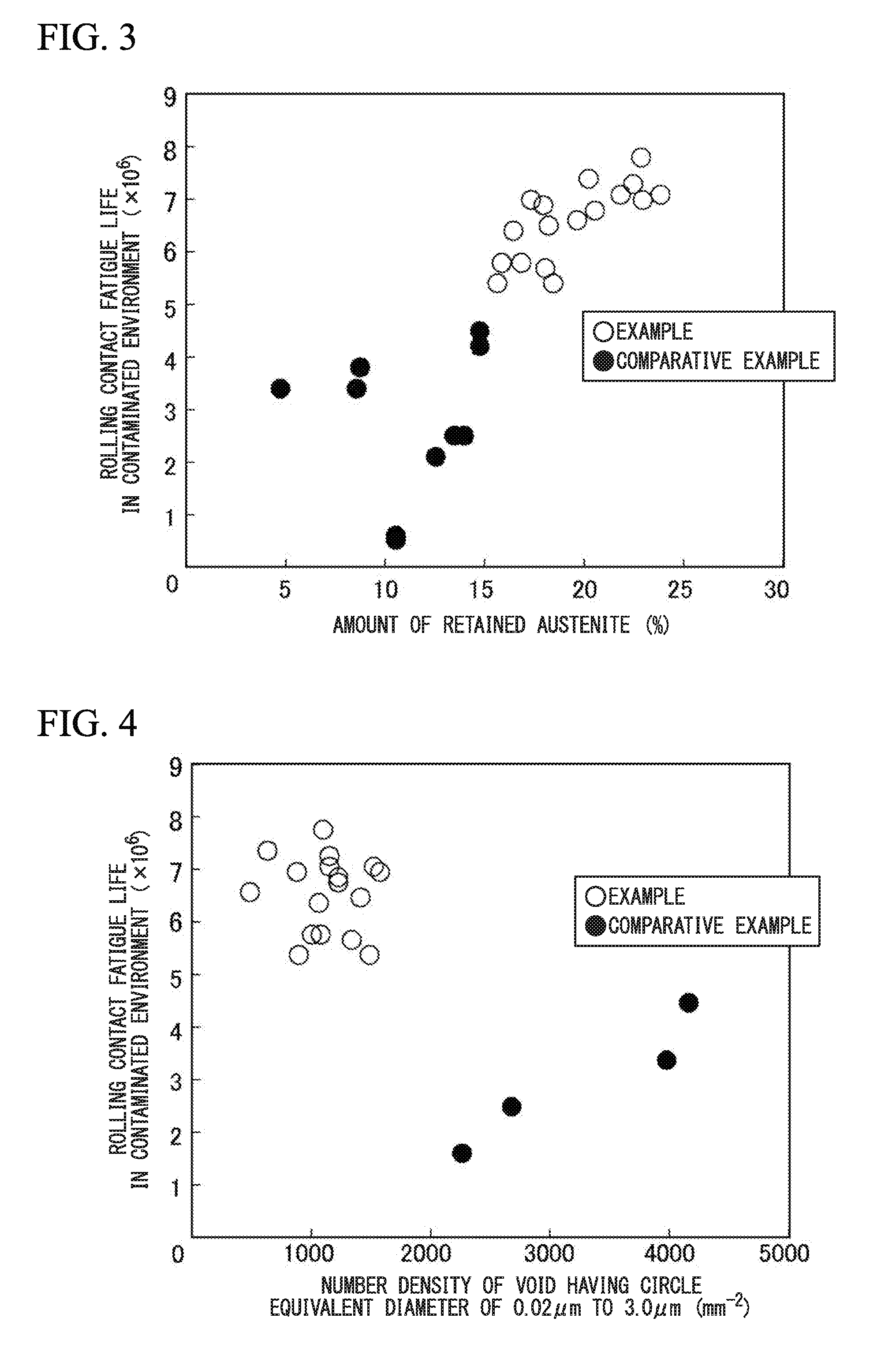
The present invention provides a bearing part that has excellent rolling contact fatigue life even in a contaminated environment. By controlling the average grain size of prior-austenite, the amount of retained austenite, and the number density of voids having a prescribed size, the bearing part achieves a long life of the machine. This results in a machine that can operate for a longer period of time without failure.

Problems solved by technology

However, there are some problems that not only a surface treatment such as carburizing or nitriding for the steel for the bearing parts is high cost, but also a variation in qualities occurs under an influence of variations in the treatment atmosphere.
As a result, a supercooled structure such as martensite generates during cooling after hot rolling; whereby workability, ductility and toughness of bearing part are deteriorated.
However, in this method disclosed in the Patent Document 2, spheroidizing annealing at high temperature for long time is performed.
As a result, C is solid-soluted into an austenite phase and a number density of spherical cementite is insufficient.
Furthermore, the average grain size of prior-austenite is coarsened and an improvement effect of rolling contact fatigue life cannot be obtained sufficiently.
Since a treatment time of spheroidizing annealing is long, when the number of times of the annealing is increased, it is known that production efficiency is deteriorated by increasing a manufacturing cost.

Method used


Image

  • Bearing part
  • Bearing part

Examples


examples

[0102]Hereinafter, effects of the bearing part according to the present embodiment will be more specifically described by using examples of the bearing part of the present invention. Here, conditions of Examples are merely examples of conditions employed to check the operability and effects of the present invention, and the present invention is not limited to the following examples of conditions. The present invention is also possible to put into practice after appropriate modifications or variations within the scope adaptable to the gist without departing from the gist of the present invention as long as the object of the present invention can be accomplished. Accordingly, the present invention can employ various conditions, and all of these conditions are contained into the technical features of the present invention.

[0103]By subjecting the wire rods or bars having components shown in Table 1 and Table 2 to heat treatment or hot forging, materials having microstructure shown in Ta...


PUM

PropertyMeasurementUnit
Lengthaaaaaaaaaa
Lengthaaaaaaaaaa
Lengthaaaaaaaaaa

Abstract

A bearing part according the present invention includes, as the chemical composition, by mass %, C: 0.95% to 1.10%, Si: 0.10% to 0.70%, Mn: 0.20% to 1.20%, Cr: 0.90% to 1.60%, Al: 0.010% to 0.100%, N: 0.003% to 0.030%, P: 0.025% or less, S: 0.025% or less, O: 0.0010% or less, and optionally Mo: 0.25% or less, B: 0.0050% or less, Cu: 1.0% or less, Ni: 3.0% or less, and Ca: 0.0015% or less, and a remainder including Fe and impurities; metallographic structure includes a retained austenite, a spherical cementite and a martensite; an amount of the retained austenite is 15% to 25%, by volume %; an average grain size of prior-austenite is 8.0 μm or less; and a number density of a void having a circle equivalent diameter of 0.02 μm to 3.0 μm is 2000 mm−2 or less in the metallographic structure.

Description

TECHNICAL FIELD OF THE INVENTION[0001]The present invention relates to a bearing part such as needle bearings and roller bearings.[0002]Priority is claimed on Japanese Patent Application No. 2014-3338, filed on Jan. 10, 2014, and Japanese Patent Application No. 2014-84952, filed on Apr. 16, 2014, the contents of which are incorporated herein by reference.RELATED ART[0003]Bearing parts such as needle bearings, roller bearings and ball bearings are continually used under a situation where a foreign material such as burr or abrasion powder is mixed into a lubricating oil, that is, are continually used in a contaminated environment. Therefore, it is important to improve rolling contact fatigue life of a bearing part in a contaminated environment. In order to improve the rolling contact fatigue life of the bearing part in a contaminated environment, it is known that an increase in retained austenite is effective. Accordingly, steel for the bearing parts is subjected to a surface treatmen...

Claims


Application Information

Patent Timeline
IPC IPC(8): C21D9/40C22C38/54C22C38/44C22C38/20C21D8/06C22C38/06C22C38/04C22C38/02C22C38/00C21D9/36F16C33/30C22C38/32
CPCC21D9/40C21D2211/008C22C38/54C22C38/44C22C38/20C22C38/32C22C38/06C22C38/04C22C38/02C22C38/002C22C38/001C21D9/36C21D8/065F16C2204/66F16C2204/70F16C2204/72F16C2220/44F16C2223/02F16C2223/10C21D2211/001C21D2211/003C21D2211/004C21D2211/005F16C33/30C22C38/18F16C33/62F16C33/64C21D9/38C22C38/40B22D23/00C21D1/18C21D1/32C22C38/22C22C38/00C22C38/08C21D9/68
Inventor SAKAMOTO, MASASHIKODAMA, JUNICHINEISHI, YUTAKA
Owner NIPPON STEEL CORP
Learn More