Bonding objects together

a technology of objects and bonding elements, applied in the field of mechanical engineering and construction, can solve the problems of new challenges in the bonding elements of these materials, substantial galvanic corrosion, and special difficulties, and achieve the effect of high shear force resistance and high ductility

Active Publication Date: 2016-11-24
WOODWELDING
View PDF2 Cites 47 Cited by
  • Summary
  • Abstract
  • Description
  • Claims
  • Application Information

AI Technical Summary

Benefits of technology

[0085]In accordance with a group of embodiments of the first sub-option, method may include the step of deforming a part of the body after the step of arranging and prior to and / or during the step of applying the mechanical vibrations to liquefy thermoplastic material of the connector. This step of deforming may especially include an expansion, i.e. an outward deformation. Especially, the in situ deformed part may include a distal broadening distally of the shaft portion and belonging to the foot portion if the connector is introduced from the proximal side and / or a proximal broadening proximally of the shaft portion and belonging to the head portion if the connector is introduced from the distal side. By this, the body may contribute to the clamping effect of the connector. The spread feature may extend into at least one radial direction further than the cross section of the shaft portion.
[0086]Mechanically deformable connectors, especially plastically deformed metal rivets, have been known in the art for a very long time. Embodiments of this group of embodiments, like all other embodiments of the present invention that include a body of a non-liquefiable material, however, have a significant advantage over the prior art. Due to the combination of a, for example, metallic (or ceramic or hard plastic or glass etc.) body with the approach of liquefying the thermoplastic material and causing it to re-solidify, the advantages of the material properties of the non-liquefiable material, such as high shear force resistance, high ductility, or also, depending on the application, other properties like electrical conductivity etc. may be used.

Problems solved by technology

The new materials cause new challenges in bonding elements of these materials—especially of bonding flattish objects (such as panels or boards) together or bonding a flattish object and an other object together, such as bonding a flattish object to another object, or bonding a connector to a flattish object.
Difficulties especially arise if objects of different materials are to be connected, such as two materials of the group including steel, aluminum, magnesium, fiber reinforced polymers—together.
Conventional rivet connections with metallic rivets firstly suffer from the drawback that the electrochemical potential of some of these materials is strongly different with differences corresponding to several volts, so that there will be substantial galvanic corrosion.
Also, connections involving flat objects of fiber reinforced polymers suffer from the additional drawback that the out-of-plane Young's modulus of these materials is very low, and the friction force arising from the compression of the objects between the rivet head and rivet foot does not substantially contribute to the mechanical stability of the connection.
However, lacquer may become brittle over time, especially when subject to long-time mechanical wear due to vibration, or it can dissolve.
However, this kind of connection is restricted to bonding thermoplastic materials and not suited for solving the above-mentioned problems.
Adhesive bonds can be light and strong but suffer from the disadvantage that there is no possibility to long-term control the reliability, since a degrading adhesive bond, for example due to an embrittling adhesive, is almost impossible to detect without entirely releasing the bond.

Method used


Image

  • Bonding objects together
  • Bonding objects together
  • Bonding objects together

Examples


Embodiment Construction

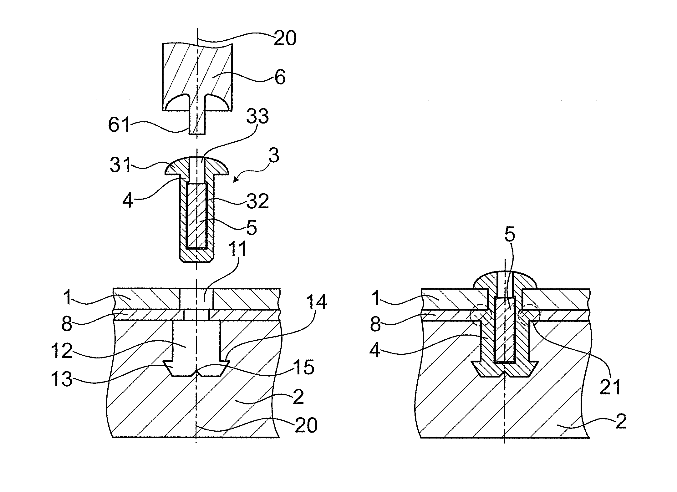
[0173]FIG. 1a depicts a basic set-up of embodiments of the invention. The first object 1 is a board or sheet, for example of a metal or of a fiber reinforced composite material. It has a first opening 11 being a through opening perpendicular to the board plane.

[0174]The second object 2 is, for example, either of a different material than the first object (for example, it may be of die-cast metal, such as die-cast magnesium or aluminum) or is (also) of a fiber-reinforced composite material, e.g. a foam filed carbon fiber reinforced sandwich element. The second object has a second opening 12 that in the depicted configuration is a blind opening. The blind opening forms an undercut 13 by having a distal broadening. Due to the distal broadening, a shoulder 14 is formed.

[0175]In the depicted configuration, there is also an optional separating / insulating layer 8 that is of a thermoplastic material. More in particular, the separating layer 8 may be of the same thermoplastic material as the...


PUM

PropertyMeasurementUnit
sizeaaaaaaaaaa
weight percentaaaaaaaaaa
Young's modulusaaaaaaaaaa

Abstract

A method of bonding a connector to a first object includes providing the connector, the connector being separate from the first object and including a thermoplastic material; arranging the first object and the connector relative to one another so that the connector reaches from a proximal side of the object through a first opening in the object; generating and applying vibrations and mechanical pressure to the connector until a flow portion of the thermoplastic material is liquefied and caused to flow sideways radially into an open space; and removing the source of the vibrations and causing the liquefied thermoplastic material to re-solidify, resulting in the connector with a foot portion, a head portion, and a shaft portion between the foot portion and the head portion. The shaft portion extends along an axis through the first opening, and secures the connector to the first object.

Description

BACKGROUND OF THE INVENTION[0001]1. Field of the Invention[0002]The invention is in the fields of mechanical engineering and construction, especially mechanical construction, for example automotive engineering, aircraft construction, shipbuilding, machine construction, toy construction etc.[0003]2. Description of Related Art[0004]In the automotive, aviation and other industries, there has been a tendency to move away from steel constructions and to use lightweight material such as aluminum or magnesium metal sheets or die-cast parts, or carbon fiber reinforced polymers instead.[0005]The new materials cause new challenges in bonding elements of these materials—especially of bonding flattish objects (such as panels or boards) together or bonding a flattish object and an other object together, such as bonding a flattish object to another object, or bonding a connector to a flattish object.[0006]Difficulties especially arise if objects of different materials are to be connected, such as...

Claims


Application Information

Patent Timeline
Patent Type & Authority Applications(United States)
IPC IPC(8): F16B17/00B29C65/00B29C65/60F16B5/04B29C65/08
CPCF16B17/002F16B5/04B29C65/08B29L2031/3076B29C66/721B29L2031/3055B29C65/601B29C65/088B29C65/562B29C65/602B29C65/603B29C66/1122B29C66/21B29C66/41B29C66/474B29C66/524B29C66/7212B29C66/723B29C66/727B29C66/7392B29C66/742B29C66/7422B29C66/81423B29C66/81429B29C66/81431B29C66/8322B29C66/83221B29C66/92445B29C66/92921F16B11/006B21J15/147B29L2031/7098B29C66/0242B29C66/73117B29C66/863B29C65/1612F16B17/00B29C65/082B29K2307/04F16B9/07
Inventor GERMANN, JONASMAYER, JORGKVIST, JOAKIMPOSCHNER, PATRICIA
Owner WOODWELDING
Why Eureka
Try Eureka